
User Guide

F-27169-6 © Copyright 2008 TAC All Rights Reserved. 5
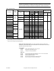
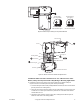
TYPICAL PROPORTIONAL CONTROL (wiring diagrams)
Figure-6 illustrates typical wiring diagrams for spring return proportional MS51-7103
actuators. See Table-1 for model selection. See 8 for wiring diagrams notes guide.
Caution:
This product contains a half-wave rectifier power supply and must not be
powered off transformers used to power other devices utilizing non-isolated full-wave
rectifier power supplies. Refer to
EN-206, Guidelines for Powering Multiple Devices from a
Common Transformer, F-26363
for detailed information.
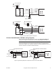
MF51-7103-xxx
Red
Black
Common
Hot (+DC)
1
Line
Volts
Controller
Blue
2
Yellow/Black
Hot
Common
3
Extend
Retract
24 Vac Transformer
or 20-30 Vdc
(-)
(+)
Feedback Signal
2 to 10 Vdc
Violet
AO
4 8
Figure-4 Triac Sink
1
Line
Volts
24 Vac Transformer
or 20-30 Vdc
MF51-7103-xxx
Red
Black
Common
Hot (+DC)
1
Line
Volts
Controller
Blue
Yellow/Black
Hot
Common
Extend
Retract
24 Vac Transformer
or 20-30 Vdc
(-)
(+)
Feedback Signal
2 to 10 Vdc
Violet
AO
2
3
4 8
Figure-5 Triac Sink With Separate Transformers
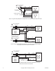
Figure-6 Typical Wiring Diagrams for Proportional Control 24 Vac Basic Models
Vdc
Feedback Signal
Red
Blk
Com
Hot (+DC)
Line
Volts
(-)
(+)
(-)
(+)
Vdc or mAdc
Control Signal
Yel/Blk
AI
1
MS51-7103-xxx
Vdc Proportional Control
Violet AO
24 Vac Transformer
or 20-30 Vdc
To Additional
2-10 Vdc
Actuators
Hot (+DC)
Red
Blk
Com
Line
Volts
(-)
(+)
Control Signal
4 to 20 mAdc
Yel/Blk
Violet
(-)
(+)
Feedback Signal
2 to 10 Vdc
4
AI
AO
MS51-7103-x00
5
1
4 to 20 mAdc with 2-10 Vdc Actuators
500 Ω
24 Vac Transformer
or 20- 30 Vdc
2
2
4
2
4
6 8
8