
User Guide


12 © Copyright 2008 TAC All Rights Reserved. F-27169-6
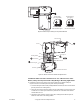
MANUAL OVERRIDE OPERATION
When necessary, the actuator’s output shaft can be repositioned using the manual override
mechanism as follows:
1. Disconnect power from the actuator. The actuator will fully retract.
2. Without pushing down on the crank, crank the manual override counterclockwise until
the actuator extends to the desired position. Push in until the mechanism locks in
position. (The manual override lock will release the next time power is applied.)
3. If you desire to reposition the actuator manually from a locked position, turn the crank
1/8 turn counterclockwise and pull out to release. Adjust position as desired.
Caution:
• Only use manual override when the actuator drive motor is not powered.
• Engaging the manual override when the actuator is powered may cause damage to the
gears.
• Using power tools to adjust the override will cause damage to the gears.
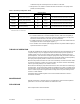
Wiring Requirements Control Leads
See Table-2 for power wiring data. Refer to Figure-1 through Figure-7 for typical wiring.
Table-2 Power Wiring
CHECKOUT
After the entire system has been installed and the actuator has been powered up, the
following check can be made for proper system operation. Check for correct operation of the
valve while actuator is being stroked.
1. Apply power to the actuator. Actuator and valve should be driven to their powered position
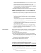
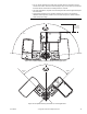
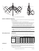
0°0°
180°
90°90°
180°
Figure-13 Unacceptable Mounting Orientation
Actuator
Voltage
Part Number
Maximum Wire Run in ft. (m)
12 AWG14 AWG16 AWG18 AWG20 AWG22 AWG
24 Vac
20-30 Vdc
MA51-7103
1678
(512)
1055
(322)
664
(202)
417
(127)
263
(80)
208
(63)
MF51-7103
1289
(393)
810
(247)
510
(155)
321
(98)
202
(61)
160
(49)
MS51-7103
1140
(348)
717
(219)
451
(137)
284
(86)
178
(54)
141
(43)