
Submittal Sheet

F-27170-6 ¤Copyright 2010 Schneider Electric All Rights Reserved. 7
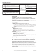
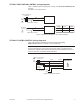
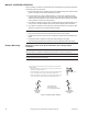
TYPICAL PROPORTIONAL CONTROL (wiring diagrams)
Figure-6 illustrates typical wiring diagrams for proportional MS4D-xxx3-xx0 actuators. See
Table-1 for model selection.
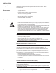
Caution: This product contains a half-wave rectifier power supply and must not be
powered off transformers used to power other devices utilizing non-isolated full-wave
rectifier power supplies. Refer to EN-206, Guidelines for Powering Multiple Devices from a
Common Transformer, F-26363 for detailed information.
Vdc
Feedback Signal
Red
Blk
Com
Hot (+DC)
Line
Volts
(-)
(+)
(-)
(+)
Vdc or mAdc
Control Signal
Yel/Blk
AI
1
MS4D-XXX3-XX0
Vdc Proportional Control
Violet AO
24 Vac Transformer
or 20-30 Vdc
To Additional
Actuators
Hot (+DC)
Red
Blk
Com
Line
Volts
(-)
(+)
Control Signal
4 to 20 mAdc
Yel/Blk
Violet
(-)
(+)
Feedback Signal
2 to 10 Vdc
4
AI
AO
MS4D-XXX3-X00
5
1
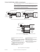
4 to 20 mAdc Proportional Control
500 Ω
24 Vac Transformer
or 20- 30 Vdc
2
2
4
2
4
6 7
7
Figure-6 Typical Wiring Diagrams for Proportional Control 24 Vac Basic Models.
Red
Blk
Com
Hot (+DC)
Line
Volts
(-)
(+)
Yel/Blk
AI
Red
Blk
Com
Hot (+DC)
Yel/Blk
AI
Violet
AO
Violet
AO
MS4D-XXX3-XX0
MS4D-XXX3-XX0
1
Control Signal
2 to 10 Vdc
24 Vac Transformer
or 20- 30 Vdc
2 3
2 3
(-)
(+)
Feedback Signal
2 to 10 Vdc
7
7
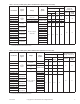
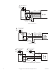
Figure-7 Typical Wiring Diagrams for Proportional Control 24 Vac Models
Wired in Parallel.
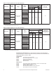
1 Provide overload protection and disconnect as
required.
2 Actuators may be wired in parallel. All actuator black
wires are connected to the transformer common and
all red wires are connected to the hot lead. Power
consumption must be observed.
3 The Common connection from the actuator must be
connected to the Hot connection of the controller. The
actuator Hot must be connected to the controller
Common.
4 If the controller uses a full-wave power supply and
does not provide isolated outputs, a separate
transformer is required.
5 A field-supplied 500 ohm resistor (AM-708) is
required for this application.
6 On MS4D-XXX3-X60 (0-20 mAdc) models a
500 resistor is incorporated in the product. Do
not use an external resistor.
7 Cable on some models contains more wires
than are used in applications. Only those
wires actually used are shown.
Figure-8 Triangle Notes for Wiring Diagrams.