
Submittal Sheet


F-27170-6 ¤Copyright 2010 Schneider Electric All Rights Reserved. 15
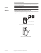
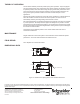
For Non-Spring Return 2-Way and 3-Way (Mx4D-8xxx)
Verify that the valve is in the desired end of stroke position. The position of the ball
opening is indicated by the index mark on top of the shaft. Verify that the actuator is at
the desired end of stroke position. Slide the actuator straight down over the valve shaft
and onto the mounting plate.
2. Align the actuator with the mounting plate, then slide the anti-rotation clip half-way into
the slot on the bottom of the actuator.
3. Tighten the wing nut to secure the anti-rotation clip in place. Be careful not to over-
tighten the wing nut.
4. Using a 1/8” hex wrench, evenly tighten the two setscrews to 50 to 60 in-lb (5.7 Nm to
6.8 Nm).
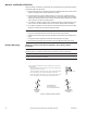
5. To reposition Base:
a. With actuator removed, remove screws.
b. Lift mounting plate while holding valve stem in position.
c. Rotate base in 45 degree increments.
d. Replace screws after reseating base in position.
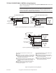
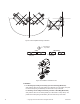
Wiring Requirements Control Leads
See Table-6 for power wiring data. Refer to Figure-1 through Figure-8 for typical wiring.
Table-5 Power Wiring.
CHECKOUT
With the correct control signals applied, power the actuator. Observe movement of the
output shaft to check for proper operation. If a spring return model, removing power should
cause the actuator to spring return to its rest position. If problems are encountered, check
the suggestions below.
Note: Check that the transformer(s) are sized properly.
• If a common transformer is used with multiple actuators, make sure that polarity is
observed on the secondary. This means connecting all black wires to one leg of the
transformer and all red wires to the other leg of the transformer.
• If multiple transformers are used with one control signal, make sure all black wires are
tied together and tied to control signal negative (-).
• If the controller uses a full-wave power supply and does not provide isolated outputs, a
separate transformer is required to power the actuator.
Actuator Voltage Part Number
Maximum Wire Run—ft. (m)
12 AWG 14 AWG
16
AWG
18
AWG
20
AWG
22
AWG
24 Vac
20 to 30 Vdc
MA4D-7033
MA4D-8033
1744
(532)
1097
(534)
690
(210)
434
(132)
273
(83)
216
(66)
MF4D-7033
MF4D-8033
1308
(399)
822
(251)
517
(158)
325
(99)
205
(62)
162
(49)
MS4D-7033
MS4D-8033
1458
(444)
917
(279)
577
(276)
363
(111)
228
(70)
181
(55)
MF4D-6083
1508
(459)
948
(289)
596
(182)
375
(114)
236
(72)
187
(57)
MS4D-6083
1710
(521)
1075
(328)
676
(206)
425
(130)
268
(82)
212
(65)
MF4D-6043
2021
(616)
1271
(387)
799
(244)
503
(153)
316
(96)
251
(76)
MS4D-6043
2118
(645)
1331
(406)
837
(255)
527
(161)
331
(101)
263
(80)