
User Guide


8 © Copyright 2008 TAC All Rights Reserved. F-26645-7
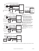
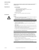
1 Provide overload protection and disconnect
as required.
2 With four actuators wired to one 500 ohm
resistor, a +2% shift of the control signal
may be required. (Actuator input impedance
is 80 k ohm.)
3 A fie
ld-supplied 500 ohm resistor (AM-708)
is required between the gray and
yellow/black leads to convert the 4 to 20
mAdc control signal to 2 to 10 Vdc.
4 Only connect common to negative (-) leg of
control circui
ts.
5 For end position indication, interlock control,
fan startup, etc., MS4X-7XX3-502 models
incorporate two built-in auxiliary switches.
6 To reverse actuator rotation, use the
reversing switch.
7 Both actuators must be
set to operate in the
same direction.
COM
5
Org/Wht
Vio/Wht
Yel/Wht
NC
COM
NO
Org
Vio
Yel
NC
NO
25 to 85°
Adjustable
5° Fixed
Aux Switches
MS4X-7073-502
MS4X-7153-502
Aux Switch 1
Aux Switch 2
Optional Auxiliary Switches
To Additional
Actuators
Grn/Yel
Hot (+DC)Red
Blk
Com
Com
Line
Volts
(-)
(+)
Control Signal
4 to 20 mA
Yel/Blk
Blu
(-)
(+)
Feedback Signal
2 to 10 Vdc
Feedback Signal
2 to 10 Vdc
4
6
Gra
L R
AI
AO
MS4X-7073
MS4X-7153
MS4X-7073-502
MS4X-7153-502
3
1
4 to 20 mAdc Proportional Control
Red
Blk
Com
Hot (+DC)
Line
Volts
(-)
(+)
Yel/Blk
AI
Red
Blk
Com
Hot (+DC)
Yel/Blk
AI
Blu
AO
6
7
MS4X-7153
MS4X-7153-502
L R
6
7
MS4X-7153
MS4X-7153-502
L R
Com
Gra
Com
Gra
Grn/Yel
Grn/Yel
1
Two Actuators on the Same Damper Shaft
Red
Blk
Com
Hot (+DC)
Line
Volts
(-)
(+)
(-)
(+)
Control Signal
2 to 10 Vdc
Control Signal
2 to 10 Vdc
Yel/Blk
AI
Grn/Yel
Com
Gra
1
6
L R
MS4X-7073
MS4X-7153
MS4X-7073-502
MS4X-7153-502
2 to 10 Vdc Proportional Control
Blu AO
500 W
24 Vac
Transformer
or 22- 30 Vdc
24 Vac
Transformer
or 22- 30 Vdc
24 Vac
Transformer
or 22- 30 Vdc
2
Figure-2 Typical Wiring Diagrams for Proportional Control 24 Vac Basic and Double Auxiliary Switch Models.