
User Guide


F-26645-7 © Copyright 2008 TAC All Rights Reserved. 25
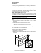
CHECKOUT
After the entire system has been installed and the actuator has been powered up, the
following check can be made for proper system operation. Check for correct operation of the
damper while actuator is being stroked.
1. Apply power to the actuator. Actuator and damper should be driven to their powered
position as determined by the control signal.
2. On the MS4X-7XXX-50X models, check for correct auxiliary switch operation.
3. Break power to the actuator. Actuator and damper should return to the spring return
position.
Note:
Check that the transformer(s) are sized properly.
• If a common transformer is used with multiple actuators, make sure that polarity is
observed on the secondary. This means connecting all Black wires to one leg of the
transformer and all Red wires to the other leg of the transformer.
• If multiple transformers are used with one control signal, make sure all Black wires are
tied together and tied to control signal negative (-).
• Controllers and actuators must have separate 24 Vac power sources.
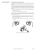
Go, No Go Test 1. Turn 24 Vac power to actuator off.
2. Disconnect and temporarily insulate the yellow/black input wire.
3. With “L” side of the actuator facing the installer, set the L/R switch to “R.”
4. Turn actuator power back on.
5. Switch the L/R switch to the “L” position.
6. The actuator should drive to the full counterclockwise position.
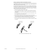
THEORY OF OPERATION
The actuators are mounted directly onto a damper shaft using a universal V-clamp. When
the actuator is powered and a Vdc or mAdc control signal is applied to the actuator by the
controller, the actuator rotates to a position determined by the control signal. At the same
time the spring return mechanism is tensed. When power is removed from the actuator, the
spring returns the actuator to its normal position. The actuators provide true mechanical
spring return operation for reliable, positive close-off on air tight dampers.
The MS40-704X-501 models are provided with one built-in auxiliary switch. The SPDT
switch is provided for interfacing or signaling, for example, fan startup. The switching
function is adjustable between 0° and 95° rotation (0 to 1 scale).
All MX4X-7XX3-XXX series actuators use a brushless DC motor which is controlled by a
microprocessor. The microprocessor supplies intelligence to provide a constant rotation rate
and to know the actuator’s exact normal position. The microprocessor monitors and controls
the brushless DC motor’s rotation and provides a digital sensing function to prevent damage
to the actuator in a stall condition. The actuator may be stalled anywhere in its normal
rotation without the need for mechanical end switches.
The MS4X-707X-502 and MS4X-715X-502 models are provided with two built-in auxiliary
switches. The SPDT switches are provided for interfacing or signaling, for example, fan
startup. The switching function is adjustable on one switch between 25° and 95° rotation,
and the other switch is fixed to operation at 5° rotation.
All MS4X-7XX3 and MS4X-7XX3-5XX actuators provide a 2 to 10 Vdc feedback signal
corresponding to the actuator position as determined by the control signal. MS40-7043-MP
and MS40-7043-MP5 models provide a 20 Vdc, 25 mA power supply used to power TAC
System 8000 controllers in lieu of position feedback.
The MS41-707X-XXX and MS41-715X-XXX actuators are equipped with a manual override
mechanism. This allows the actuator to be manually positioned at any point between -5° and
85° rotation. This mechanism is accessible on both sides of the actuator and can be used to
ensure tight close-offs for valves and dampers. The manual override should not be used
while a unit is powered or on units that are mounted in tandem.