
User Guide


F-26645-7 © Copyright 2008 TAC All Rights Reserved. 21
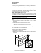
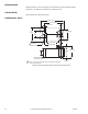
Wiring Requirements Control Leads
See Table-3 for power wiring data. Refer to Figure-1 and Figure-2 for typical wiring.
Table-3 Power Wiring.
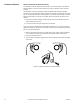
Auxiliary Switch The MS40-7043-501(-MP5) series actuators include one built-in SPDT auxiliary switch
which can be used for interfacing or signaling (e.g., for fan start-up). The switch is adjustable
between 0° and 95° of rotation (0 to 1 scale).
The MS4X-7153-502 and MS4X-7073-502 series actuators include two built-in SPDT
auxiliary switches which can be used for interfacing or signaling (e.g., for fan start-up). The
switch position near the normal (spring return) position is fixed at 5°. The other is adjustable
between 25° and 85° of rotation.
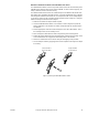
Adjusting the Switching Point
Refer to Table-4 for auxiliary switch rating.
Adjusting the switching point for MS40-7043-501 (-MP5)
1. The actuator must be in its normal (spring return) position.
2. Use a flat screw driver to rotate the switch pointer until it is at the desired switch position
on the 0 to 1 scale.
Adjusting the switching point for MS4X-7153-502 or MS4X-7073-502
1. The actuator must be in its normal (spring return) position.
2. Insert a 1/8" allen wrench into the hex hole located in the center of the adjustable switch
pointer.
3. Rotate the wrench until the switch pointer is at the desired switch position in degrees,
from 25 to 85°.
Table-4 Auxiliary Switch Rating.
Actuator
Voltage
Part Number
Maximum Wire Run in ft. (m)
12 AWG14 AWG16 AWG18 AWG20 AWG22 AWG
24 Vac
22-30 Vdc
MS40-7043 (-MP)
1100
(335)
700
(213)
430
(131)
270
(82)
170
(52)
110
(34)
MS40-7043-501
(MP5)
MS4X-7073
1000
(305)
640
(195)
400
(122)
250
(76)
160
(49)
100
(30)
MS4X-7073-502
MS4X-7153
600
(183)
380
(116)
240
(73)
150
(46)
90
(27)
60
(18)
MS4X-7153-502
Part Number Voltage Resistive Load Inductive Load
MS40-7043-501 (MP5) 24 Vac 6A 1.5A
MS4X-7073-502
250 Vac 7A 2.5A
MS4X-7153-502