
User Guide


F-26645-7 © Copyright 2008 TAC All Rights Reserved. 15
MS4X-707X and MS4X-715X Series Installation
Caution:
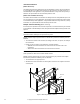
Do not drill additional holes in the actuator body. Six pre-drilled holes are located
on each side, under the label, to accept #10-24 thread-forming screws for mounting
accessories.
Note:
The MS4X-707X and MS4X-715X series actuators come equipped with standard
universal mounting clamp installed. For damper shafts larger than 3/4" (19 mm) in
diameter, the AM-687 universal mounting clamp is required (order separately). The
AM-687 clamp accommodates round shaft sizes up to 1.05" (27 mm) in diameter or 5/8"
(16 mm) square shafts.
Caution:
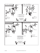
The MS41-707X and MS41-715X actuators are equipped with a manual
override.
• The manual override to be used only when power is not applied to the unit.
• If the universal clamp is not set to 0° on the position indicator, manually wind the
actuator in the direction indicated with hex wrench from -5° to 0° and lock with a
screwdriver.
• When operating manual override, back off 5° from full open mechanical stop to ensure
proper release.
• Do not attempt to use the manual override with actuators mounted in tandem. Damage
to the gear train could occur.
• Using power tools to adjust the manual override will cause damage to the gears.
• To unlock manual override without power, crank the manual override in the direction
indicated a minimum of 5°.
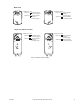
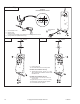
E- Left
E - Right
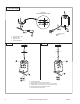
15. Tighten bracket screws.
x 2
15
9
1
.8
.6
.4
.2
0
R
x 2
15
12
1
.8
.6
.4
.2
0
L
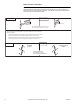
Correct clamp mounting
position
(after 5˚ preload)
L
.4
.2
0
R
.4
.2
0