
Product Overview


F-24789-7 © Copyright 2008 TAC All Rights Reserved. 9
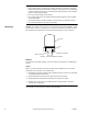
Wiring Requirements Control Leads
The control leads may be connected to a Class 2 circuit if routed separately from Class 1
circuit wiring. Refer to Figure-9.
Refer to Table-4 for the maximum wire run of the control leads.
Caution:
• Use three-conductor, twisted, shielded wire when it becomes necessary to install the
control leads in the same conduit with power wiring or when RFI/EMI generating
devices are near.
• Do not connect the shield or conduit to earth ground.
Table-4 Control Wiring Data.
Power Leads
The low voltage (24 Vac) power leads may be connected to a Class 2 circuit if routed
separately from Class 1 circuit wiring. Refer to Figure-9. Line voltage power leads must be
connected to a Class 1 circuit.
Refer to Table-5 for maximum length of run for given wire size(s). To determine the
allowable maximum power lead run for multiple actuator wiring, divide the maximum run
shown in Table-5 by the number of actuators on the run.
Table-5 Power Wiring Data.
Wire Size
GA
Maximum Wire Run
ft. (m)
18 1000 (304.8)
16 2250 (685.8)
14 4000 (1219.1)
Actuator
Voltage
Vac
Actuator Model
Number
Power Lead
Colors
Wire Size
GA
Maximum Wire Run
ft. (m)
120
MP-52x0
Black & White
14
3500
(1067)
MP-5210-500
240
MP-52x1
Black & White/Black
6000
(1829)
MP-5211-500
24
MP-52x3
Black & Black/Blue
300
(91.5)
MP-5213-500
24
MP-52x3
Black & Black/Blue 12
480
(146.3)
MP-5213-500