
User Guide


8 Copyright 2008 TAC All Rights Reserved. F-24789-7
Caution:
• Static charges produce voltages high enough to damage the electronic components.
Follow static electricity precautions when installing or servicing the device(s). Discharge
any static electricity you may have accumulated by using wrist straps, or by touching a
known, securely grounded object.
• Do not exceed the ratings of the device(s).
• Do not apply power to the unit unless the damper linkage and/or the valve assembly
have been installed.
• Avoid locations where excessive moisture, corrosive fumes, or vibration is present.
• Do not install insulation on any part of the actuator.
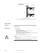
Mounting
Caution:
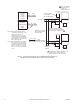
Do not twist or exert any force on the actuator housing during installation. Either
turn the base by hand or, if necessary, use a 1-5/8" open-ended wrench (TOOL-37) on the
flats provided on the actuator base or the valve body mounting nut. Refer to Figure-5.
Dampers
The actuator is not position sensitive. It can be mounted in any position in a NEMA Type 1
location.
Valves
Allow 3" (76 mm) of clearance above the actuator valve assembly for the removal and
reattachment of the actuator to the installed valve.
1. Install all two-way valves so that they close against the flow. An arrow on the valve body
or tag indicates proper flow direction.
2. Always install three-way mixing valves with two inlets and one outlet.
3. Always install three-way diverting valves with one inlet and two outlets.
4. Actuators can be mounted in any upright position to approximately 5° above the
centerline of the valve body.
Caution:
For steam applications only, mount the actuator above the valve body at
approximately 45° from vertical for maximum heat dissipation.
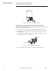
Housing
Base
Wrench Flats
Position Indicato
r
Figure-5 Housing and Base Location.