
User Guide


F-24789-7 © Copyright 2008 TAC All Rights Reserved. 7
INSTALLATION
Inspection Inspect the package for damage. If damaged, notify the appropriate carrier immediately.
If undamaged, open the package and inspect the device for obvious damage. Return
damaged products.
Requirements • Job wiring diagrams
• Tools (not provided):
– Digital Volt-ohm Meter (DVM)
– Appropriate drill and drill bit for mounting screws on dampers
– Appropriate screw drivers and wrenches
– TOOL-12, Wrench for adjustment of auxiliary switch
– TOOL-19, Spring compression tool for AV-600 when used on VB-9xxx valves only
– TOOL-37, 1-5/8" open-ended wrench
• Training: Installer must be a qualified, experienced technician
Warning:
• Disconnect power at breaker or fuse before installation to prevent electrical shock and
equipment damage.
• Make all connections in accordance with the wiring diagram and in accordance with
national and local electrical codes.
Use copper conductors only.
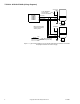
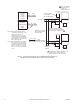
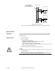
To Vac Power
Black
Green
Green
MP-52XX
MP-52XX
To additional
MP-52XX Series Actuator
24 Vac Black/Blue
120 Vac White
240 Vac White/Black
Figure-4 Wiring of Multiple MP-5200 Series Actuators to Single Power Source.