
User Guide


F-24789-7 © Copyright 2008 TAC All Rights Reserved. 15
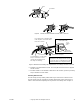
5. Rotate the damper to its open position. Install and secure the damper crank arm
(with ball joint connector) to the damper shaft, positioning the crank arm as follows
(refer to Figure-16):
a. To achieve 60° of damper rotation, position the crank arm so that it is pointed
towards the actuator at 30° from its mid-stroke position.
b. To achieve 90° of damper rotation, position the crank arm so that it is pointed
towards the actuator at 45° from its mid-stroke position.
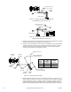
6. Install the damper rod by sliding one end through the ball joint connector mounted on
the damper crank arm, and the other end through the straight connector on the actuator
crank arm. Tighten the nut on the actuator crank arm’s straight connector. Cut off any
excess length of damper rod.
7. For normally open dampers, tighten the nut on the ball joint connector on the damper
crank arm. To ensure that the damper closes completely, make adjustments so that the
actuator is 1/16" (1.6 mm) from the extended end of stroke when the damper closes.
Verify and, if necessary, make final adjustments during system checkout.
8. For normally closed dampers, rotate the damper crank arm until the damper is closed.
While holding the damper closed, tighten the nut on the ball joint connector on the
damper crank arm. To ensure that the damper closes completely, make adjustments so
that the actuator is 1/16" (1.6 mm) from the retracted end of stroke when the damper
closes.
Final adjustment of the actuator and damper must be performed when the system is
powered and functioning. Refer to the CHECKOUT section to ensure that the damper is
linked correctly.
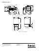
Valve
For valve assembly details refer to
AV-600, Valve Linkage Kit General Instructions, F-26279
for VB-9xxx valves, or
AV-7600-1, Valve Linkage Kit General Instructions, F-26235
for
VB-7xxx valves, with
AV-601, Linkage Extension Kit General Instructions, F-26280
. Refer to
Figure-22 for external dimensions of the valve actuator.
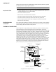
Adjustments Auxiliary Switch (MP-52xx-500)
The switching point is adjustable over the entire actuator stroke and is pre-set at the factory
to close the N.C. contacts at the retracted end of stroke. Turning the switch adjustment
screw CW (using TOOL-12), adjusts the make (or break) point closer to the extended end
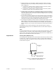
of stroke. Refer to Figure-17.
Figure-17 Auxiliary Switch Point Adjustment and
Position Indication for MP-5200 Series.
Position Indication and
Switch Action Cam
Auxiliary Switch
Adjustment Screw
MP-52XX-500
Series