
User Guide

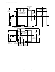
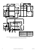
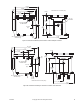


Table Of Contents
- Application
- Features
- Applicable Literature
- SPECIFICATIONS
- ACCESSORIES
- TYPICAL APPLICATIONS (wiring diagrams)
- List of Figures
- Typical Actuators: MP-361, MP-371, MP-381, MP-382, and MP-2113-500.
- Typical Actuators: MP-421, MP-422, MP-423, MP-424, MP-451, MP-452, MP-4553, MP-454, MP-465, MP-483, MP-485, MP-486, MP-495, MP-2130-500, MP-2150-500, MP5-2151-500, MP5-4651, MP5-4751, MP-4851, and MP5-4851.
- Typical Actuators: MP-361, MP-371, MP-381, MP-382, and MP-2113-500.
- Typical TAC Microtherm Controllers: PP-22x Series, TP-2xx Series, TP-3xx Series, TP-4xx Series, and TP-101x Series.
- Typical Cooling TAC Microtherm: TP-1031.
- Typical TAC Microtherm Controllers: PP-22x Series, TP-2xx Series, TP-3xx Series, TP-4xx Series, and TP-101x Series.
- Typical Actuators: MP-465, MP-475, MP-485, MP-486, MP-495, MP-2130-500, MP-2150-500, MP5-2151-500, MP5-4651, MP5-4751, MP-4851, and MP5-4851.
- Typical TAC Microtherm Controllers: PP-22x Series, TP-2xx Series, TP-3xx Series, TP-4xx Series, and TP-101x Series.
- Typical Cooling TAC Microtherm: TP-1031.
- Typical Actuators: MP-465, MP-475, MP-485, MP-486, MP-495, MP-2130-500, MP-2150-500, MP5-2151-500, MP5-4651, MP5-4751, MP-4851, and MP5-4851.
- Typical TAC Microtherm Controllers: PP-22x Series, TP-2xx Series, TP-3xx Series, TP-4xx Series, and TP-101x Series.
- Typical Actuators: MP-367, MP-377, and MP-387.
- Typical TAC Microtherm Controllers: PP-22x Series, TP-2xx Series, TP-3xx Series, TP-4xx Series, and TP-101x Series.
- Sequence of Operation
- Typical TAC Microtherm Controllers: TP-2xx Series, TP-3xx Series, and TP-4xx Series.
- Cycle of Operation
- Typical TAC Microtherm Controllers: TP-2xx Series, TP-3xx Series, and TP-4xx Series.
- Cycle of Operation
- Typical Actuators which require AE-504 purchased separately: MP-361, MP-371, MP-382, and MP-2113-500.
- Typical Actuators which require AE-504 purchased separately: MP-465, MP-475, MP-483, MP-485, MP-486, MP-495, MP-2130-500, MP-2150-500, MP5-4651, MP5-4751, MP-4851, MP5-4851.
- Typical Actuators which require CP-8301-120 purchased separately: MP-421, MP-422, MP-423, MP-424, MP-451, MP-452, MP-454.
- Typical Actuators with CP-8301-120 factory installed and wired: MP-461-600, MP-471-600, MP-481-600, MP-2110-601.
- Typical Actuators which require CP-8301-024 purchased separately: MP-361, MP-371, MP-381, MP-382, MP-2113-500.
- Typical Actuators which require CP-8301-120 purchased separately: MP-465, MP-475, MP-483, MP-485, MP-486, MP495, MP-2130-500, MP-2150-500.
- Typical Actuators which require CP-8301-240 purchased separately: MP5-2151-500, MP5-4651, MP5-4751, MP-4851, MP5-4851.
- Typical Actuators which require CP-8391-913 purchased separately: MP-361, MP-371, MP-381, MP-382, MP-2113-500.
- Typical Actuators which require CP-8391-910 purchased separately: MP-421, MP-422, MP-424, MP-451, MP-452, MP-453, MP-454.
- Typical Actuators which require CP-8391-910 purchased separately: MP-465, MP-475, MP483, MP-485, MP-486, MP-495, MP-2130-500, MP-2150-500.
- Typical Actuators which require CP-8391-716 purchased separately: MP-421, MP-422, MP-423, MP-424, MP-451, MP-452, MP-453, MP-454.
- Typical 120 Vac Actuators which require CP-8391-716 purchased separately: MP-465, MP-475. MP-483, MP-485, MP-486, MP-495, MP-2130-500, MP-2150-500.
- Typical 240 Vac Actuators which require CP-8391-716 purchased separately: MP5-2151-500, MP5-4651, MP5-4751, MP-4851, MP5-4851.
- Typical Actuators: MP-361, MP-371, MP-381, and MP-382.
- Typical Actuators: MP-421, MP-422, MP-423, MP-424, MP-451, MP-452, MP-453, MP-454, MP-461-600, MP-471-600, and MP-481-600.
- Typical Actuators: MP-465, MP-475, MP-483, MP-486, MP-495, MP5-4651, MP5-4751, MP-4851, and MP5-4851.
- Typical Actuator: MP-2113-500.
- Typical Actuator: MP-2110-600.
- Typical Actuators: MP-2130-500, MP-2150-500, MP5-2151-500.
- Typical Actuators: MP-379 and MP-389
- Typical Actuators: MP-470, MP-480, and MP-4701.
- Typical Actuators: MP-367, MP-377, and MP-387.
- List of Figures
- INSTALLATION
- MOUNTING
- WIRING
- ADJUSTMENTS
- CHECKOUT
- GO, NO GO Test
- Slidewire Controller with 24 Vac Actuators
- Slidewire Controller with Line Voltage Actuator
- CP-8301-120, Vdc Interface (TAC System 8000) with Line Voltage Actuators without Internal Transformer
- CP-8301-024, Vdc Interface (TAC System 8000) with 24 Vac Actuators
- CP-8301-120 and CP-8301-240, Vdc Interface (TAC System 8000) with Line Voltage Actuators with Internal Transformer
- CP-8391-xxx Series mAdc Interface
- Positioning the Actuator with the Controller
- GO, NO GO Test
- REPLACEMENT PARTS
- MAINTENANCE
- TROUBLESHOOTING
- REPAIR
- DIMENSIONAL DATA

F-15479-8 © Copyright 2007 TAC All Rights Reserved. 41
Positioning the
Actuator with the
Controller
If the sensed media is within the controller’s setpoint range, the actuator can be positioned
by adjusting the controller setpoint up and down. Check for proper operation of the actuator
(valve or damper) while the actuator is being stroked.
Manually Positioning with Calibration Kit
TOOL-201, Calibration Kit for TAC System 8000, Vdc Input
Refer to Figure-16 through Figure-18.
1. Disconnect the field wiring from the Red, Yellow, and Blue leads of CP-8301-xxx.
2. Attach the Red, Yellow, and Blue leads of TOOL-201 to the same color leads on the
CP-8301-xxx.
3. The actuator can be manually positioned by turning the knob of TOOL-201.
4. Check for proper operation of the valve or damper as the actuator is operated.
5. Disconnect TOOL-201 and reconnect the field wiring.
Theory of Operation
Actuator variations are shown in Figure-24 through Figure-32. Refer to the actuator
selection tables beginning on page 3 to determine which Internal Wiring Figure applies to a
certain actuator.
The actuators are powered by shaded pole motors that are of the induction type, using what
is commonly know as a squirrel cage rotor. These motors, like all single phase induction
motors, must be provided with some means of starting. This is accomplished by the shading
coils in the poles of the motor and hence the name “Shaded Pole.” However, unlike most
single phase induction motors, the shading coils are also essential for running.
The field coil produces a magnetic field in the iron core (stator) and in the rotor. When
actuator terminal x is shorted to a terminal attached to CW shading coils, it causes a lag in
part of the field which provides the equivalent of a rotating field. This rotating field induces a
voltage and current in the rotor bars, and the attraction between the rotating field and these
current carrying bars pulls the rotor around with the field in a CW direction. When actuator
terminal x is shorted to a terminal attached to CCW shading coils, it operates the same
except it drives the actuator CCW. A voltage of 24 to 30 Vac with current of 9 amps is induced
in the shading coils in much the same manner as the secondary of a transformer.