
User Guide
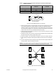
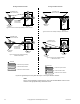


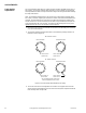
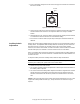
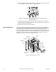
Table Of Contents
- Application
- Features
- Applicable Literature
- SPECIFICATIONS
- ACCESSORIES
- TYPICAL APPLICATIONS (wiring diagrams)
- List of Figures
- Typical Actuators: MP-361, MP-371, MP-381, MP-382, and MP-2113-500.
- Typical Actuators: MP-421, MP-422, MP-423, MP-424, MP-451, MP-452, MP-4553, MP-454, MP-465, MP-483, MP-485, MP-486, MP-495, MP-2130-500, MP-2150-500, MP5-2151-500, MP5-4651, MP5-4751, MP-4851, and MP5-4851.
- Typical Actuators: MP-361, MP-371, MP-381, MP-382, and MP-2113-500.
- Typical TAC Microtherm Controllers: PP-22x Series, TP-2xx Series, TP-3xx Series, TP-4xx Series, and TP-101x Series.
- Typical Cooling TAC Microtherm: TP-1031.
- Typical TAC Microtherm Controllers: PP-22x Series, TP-2xx Series, TP-3xx Series, TP-4xx Series, and TP-101x Series.
- Typical Actuators: MP-465, MP-475, MP-485, MP-486, MP-495, MP-2130-500, MP-2150-500, MP5-2151-500, MP5-4651, MP5-4751, MP-4851, and MP5-4851.
- Typical TAC Microtherm Controllers: PP-22x Series, TP-2xx Series, TP-3xx Series, TP-4xx Series, and TP-101x Series.
- Typical Cooling TAC Microtherm: TP-1031.
- Typical Actuators: MP-465, MP-475, MP-485, MP-486, MP-495, MP-2130-500, MP-2150-500, MP5-2151-500, MP5-4651, MP5-4751, MP-4851, and MP5-4851.
- Typical TAC Microtherm Controllers: PP-22x Series, TP-2xx Series, TP-3xx Series, TP-4xx Series, and TP-101x Series.
- Typical Actuators: MP-367, MP-377, and MP-387.
- Typical TAC Microtherm Controllers: PP-22x Series, TP-2xx Series, TP-3xx Series, TP-4xx Series, and TP-101x Series.
- Sequence of Operation
- Typical TAC Microtherm Controllers: TP-2xx Series, TP-3xx Series, and TP-4xx Series.
- Cycle of Operation
- Typical TAC Microtherm Controllers: TP-2xx Series, TP-3xx Series, and TP-4xx Series.
- Cycle of Operation
- Typical Actuators which require AE-504 purchased separately: MP-361, MP-371, MP-382, and MP-2113-500.
- Typical Actuators which require AE-504 purchased separately: MP-465, MP-475, MP-483, MP-485, MP-486, MP-495, MP-2130-500, MP-2150-500, MP5-4651, MP5-4751, MP-4851, MP5-4851.
- Typical Actuators which require CP-8301-120 purchased separately: MP-421, MP-422, MP-423, MP-424, MP-451, MP-452, MP-454.
- Typical Actuators with CP-8301-120 factory installed and wired: MP-461-600, MP-471-600, MP-481-600, MP-2110-601.
- Typical Actuators which require CP-8301-024 purchased separately: MP-361, MP-371, MP-381, MP-382, MP-2113-500.
- Typical Actuators which require CP-8301-120 purchased separately: MP-465, MP-475, MP-483, MP-485, MP-486, MP495, MP-2130-500, MP-2150-500.
- Typical Actuators which require CP-8301-240 purchased separately: MP5-2151-500, MP5-4651, MP5-4751, MP-4851, MP5-4851.
- Typical Actuators which require CP-8391-913 purchased separately: MP-361, MP-371, MP-381, MP-382, MP-2113-500.
- Typical Actuators which require CP-8391-910 purchased separately: MP-421, MP-422, MP-424, MP-451, MP-452, MP-453, MP-454.
- Typical Actuators which require CP-8391-910 purchased separately: MP-465, MP-475, MP483, MP-485, MP-486, MP-495, MP-2130-500, MP-2150-500.
- Typical Actuators which require CP-8391-716 purchased separately: MP-421, MP-422, MP-423, MP-424, MP-451, MP-452, MP-453, MP-454.
- Typical 120 Vac Actuators which require CP-8391-716 purchased separately: MP-465, MP-475. MP-483, MP-485, MP-486, MP-495, MP-2130-500, MP-2150-500.
- Typical 240 Vac Actuators which require CP-8391-716 purchased separately: MP5-2151-500, MP5-4651, MP5-4751, MP-4851, MP5-4851.
- Typical Actuators: MP-361, MP-371, MP-381, and MP-382.
- Typical Actuators: MP-421, MP-422, MP-423, MP-424, MP-451, MP-452, MP-453, MP-454, MP-461-600, MP-471-600, and MP-481-600.
- Typical Actuators: MP-465, MP-475, MP-483, MP-486, MP-495, MP5-4651, MP5-4751, MP-4851, and MP5-4851.
- Typical Actuator: MP-2113-500.
- Typical Actuator: MP-2110-600.
- Typical Actuators: MP-2130-500, MP-2150-500, MP5-2151-500.
- Typical Actuators: MP-379 and MP-389
- Typical Actuators: MP-470, MP-480, and MP-4701.
- Typical Actuators: MP-367, MP-377, and MP-387.
- List of Figures
- INSTALLATION
- MOUNTING
- WIRING
- ADJUSTMENTS
- CHECKOUT
- GO, NO GO Test
- Slidewire Controller with 24 Vac Actuators
- Slidewire Controller with Line Voltage Actuator
- CP-8301-120, Vdc Interface (TAC System 8000) with Line Voltage Actuators without Internal Transformer
- CP-8301-024, Vdc Interface (TAC System 8000) with 24 Vac Actuators
- CP-8301-120 and CP-8301-240, Vdc Interface (TAC System 8000) with Line Voltage Actuators with Internal Transformer
- CP-8391-xxx Series mAdc Interface
- Positioning the Actuator with the Controller
- GO, NO GO Test
- REPLACEMENT PARTS
- MAINTENANCE
- TROUBLESHOOTING
- REPAIR
- DIMENSIONAL DATA

F-15479-8 © Copyright 2007 TAC All Rights Reserved. 35
Control Wiring Refer to Figure-3 through Figure-23 for typical wiring of the actuators. Refer to the actuator
selection tables beginning on page 3, for an index of External Wiring Figures versus actuator
models and control signals. The requirements for the field control wiring are shown below.
SPST Control Signal
Refer to Figure-3 and Figure-4. Since the SPST switch is controlling the power to the
actuator, the control wiring is limited to the power wiring shown above.
SPDT Control Signal
Refer to Figure-5 and Figure-6. Use 18 gage wire for runs up to 1,000 ft. (305 m) between
the actuator and the SPDT switch. Use larger gage wires on longer runs.
TAC Microtherm Control
Refer to External Wiring Figure-7 through Figure-13. Use 18 gage wire for runs up to
1,000 ft. (305 m) between the actuator and the TAC Microtherm controller. Use larger gage
wires on longer runs.
135 to 1000 Ω Slidewire Control
Refer to External Wiring Figure-14 and Figure-15. Use 18 gage three-conductor twisted
leads (part number W-103 or equal) for runs up to 500 ft. (152 m) between the actuator and
the slidewire controller. Use larger gage wires for longer runs.
Voltage Vdc (TAC System 8000) Control
Refer to External Wiring Figure-16 through Figure-18. Use 18 gage three-conductor twisted
leads (part number W-103 or equal) for runs up to 1,000 ft. (305 m) between the actuator
and the Vdc (TAC System 8000) controller. Use larger gage wires for longer runs.
Caution: Use 18 gage three-conductor shielded cable (twisted) when it is necessary to
install the control leads in the same conduit with power wiring, or when high RFI/EMI
generating devices are near. Do not connect the shield to earth ground or any leads or
terminals.
Current mAdc Control
Refer to External Wiring Figure-19 through Figure-23. Use 18 gage two-conductor twisted
leads (part number W-102 or equal) for runs up to 500 ft. (152 m) between the actuator and
the slidewire controller. Use larger gage wires for longer runs.
Direct Digital Control (DDC)
DDC controllers may be used to control these actuators according to one of the methods
described below.
SPST Control
Refer to External Wiring Figure-5 and Figure-6. Requires two digital output points
programmed as a drive open, drive closed configuration. The digital output must be rated for
switching 0.9
amp at 24 Vac.
Voltage Vdc Control
Refer to External Wiring Figure-16, Figure-17, and Figure-18. Requires an analog output
from the DDC controller, programmed to provide the desired voltage range. Also requires a
CP-8301-120 electronic actuator drive between the DDC controller and the actuator.
Current mAdc Control
Refer to External Wiring Figure-19, Figure-20, and Figure-21. Requires an analog output
from the DDC controller, programmed to provide the desired current range (usually 4 to 20
mA). Also requires a CP-8391-913 electronic actuator drive between the DDC controller and
the actuator.