
User Guide
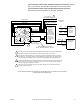
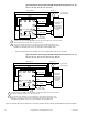
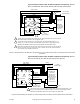

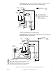
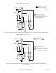
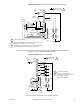
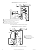
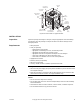

Table Of Contents
- Application
- Features
- Applicable Literature
- SPECIFICATIONS
- ACCESSORIES
- TYPICAL APPLICATIONS (wiring diagrams)
- List of Figures
- Typical Actuators: MP-361, MP-371, MP-381, MP-382, and MP-2113-500.
- Typical Actuators: MP-421, MP-422, MP-423, MP-424, MP-451, MP-452, MP-4553, MP-454, MP-465, MP-483, MP-485, MP-486, MP-495, MP-2130-500, MP-2150-500, MP5-2151-500, MP5-4651, MP5-4751, MP-4851, and MP5-4851.
- Typical Actuators: MP-361, MP-371, MP-381, MP-382, and MP-2113-500.
- Typical TAC Microtherm Controllers: PP-22x Series, TP-2xx Series, TP-3xx Series, TP-4xx Series, and TP-101x Series.
- Typical Cooling TAC Microtherm: TP-1031.
- Typical TAC Microtherm Controllers: PP-22x Series, TP-2xx Series, TP-3xx Series, TP-4xx Series, and TP-101x Series.
- Typical Actuators: MP-465, MP-475, MP-485, MP-486, MP-495, MP-2130-500, MP-2150-500, MP5-2151-500, MP5-4651, MP5-4751, MP-4851, and MP5-4851.
- Typical TAC Microtherm Controllers: PP-22x Series, TP-2xx Series, TP-3xx Series, TP-4xx Series, and TP-101x Series.
- Typical Cooling TAC Microtherm: TP-1031.
- Typical Actuators: MP-465, MP-475, MP-485, MP-486, MP-495, MP-2130-500, MP-2150-500, MP5-2151-500, MP5-4651, MP5-4751, MP-4851, and MP5-4851.
- Typical TAC Microtherm Controllers: PP-22x Series, TP-2xx Series, TP-3xx Series, TP-4xx Series, and TP-101x Series.
- Typical Actuators: MP-367, MP-377, and MP-387.
- Typical TAC Microtherm Controllers: PP-22x Series, TP-2xx Series, TP-3xx Series, TP-4xx Series, and TP-101x Series.
- Sequence of Operation
- Typical TAC Microtherm Controllers: TP-2xx Series, TP-3xx Series, and TP-4xx Series.
- Cycle of Operation
- Typical TAC Microtherm Controllers: TP-2xx Series, TP-3xx Series, and TP-4xx Series.
- Cycle of Operation
- Typical Actuators which require AE-504 purchased separately: MP-361, MP-371, MP-382, and MP-2113-500.
- Typical Actuators which require AE-504 purchased separately: MP-465, MP-475, MP-483, MP-485, MP-486, MP-495, MP-2130-500, MP-2150-500, MP5-4651, MP5-4751, MP-4851, MP5-4851.
- Typical Actuators which require CP-8301-120 purchased separately: MP-421, MP-422, MP-423, MP-424, MP-451, MP-452, MP-454.
- Typical Actuators with CP-8301-120 factory installed and wired: MP-461-600, MP-471-600, MP-481-600, MP-2110-601.
- Typical Actuators which require CP-8301-024 purchased separately: MP-361, MP-371, MP-381, MP-382, MP-2113-500.
- Typical Actuators which require CP-8301-120 purchased separately: MP-465, MP-475, MP-483, MP-485, MP-486, MP495, MP-2130-500, MP-2150-500.
- Typical Actuators which require CP-8301-240 purchased separately: MP5-2151-500, MP5-4651, MP5-4751, MP-4851, MP5-4851.
- Typical Actuators which require CP-8391-913 purchased separately: MP-361, MP-371, MP-381, MP-382, MP-2113-500.
- Typical Actuators which require CP-8391-910 purchased separately: MP-421, MP-422, MP-424, MP-451, MP-452, MP-453, MP-454.
- Typical Actuators which require CP-8391-910 purchased separately: MP-465, MP-475, MP483, MP-485, MP-486, MP-495, MP-2130-500, MP-2150-500.
- Typical Actuators which require CP-8391-716 purchased separately: MP-421, MP-422, MP-423, MP-424, MP-451, MP-452, MP-453, MP-454.
- Typical 120 Vac Actuators which require CP-8391-716 purchased separately: MP-465, MP-475. MP-483, MP-485, MP-486, MP-495, MP-2130-500, MP-2150-500.
- Typical 240 Vac Actuators which require CP-8391-716 purchased separately: MP5-2151-500, MP5-4651, MP5-4751, MP-4851, MP5-4851.
- Typical Actuators: MP-361, MP-371, MP-381, and MP-382.
- Typical Actuators: MP-421, MP-422, MP-423, MP-424, MP-451, MP-452, MP-453, MP-454, MP-461-600, MP-471-600, and MP-481-600.
- Typical Actuators: MP-465, MP-475, MP-483, MP-486, MP-495, MP5-4651, MP5-4751, MP-4851, and MP5-4851.
- Typical Actuator: MP-2113-500.
- Typical Actuator: MP-2110-600.
- Typical Actuators: MP-2130-500, MP-2150-500, MP5-2151-500.
- Typical Actuators: MP-379 and MP-389
- Typical Actuators: MP-470, MP-480, and MP-4701.
- Typical Actuators: MP-367, MP-377, and MP-387.
- List of Figures
- INSTALLATION
- MOUNTING
- WIRING
- ADJUSTMENTS
- CHECKOUT
- GO, NO GO Test
- Slidewire Controller with 24 Vac Actuators
- Slidewire Controller with Line Voltage Actuator
- CP-8301-120, Vdc Interface (TAC System 8000) with Line Voltage Actuators without Internal Transformer
- CP-8301-024, Vdc Interface (TAC System 8000) with 24 Vac Actuators
- CP-8301-120 and CP-8301-240, Vdc Interface (TAC System 8000) with Line Voltage Actuators with Internal Transformer
- CP-8391-xxx Series mAdc Interface
- Positioning the Actuator with the Controller
- GO, NO GO Test
- REPLACEMENT PARTS
- MAINTENANCE
- TROUBLESHOOTING
- REPAIR
- DIMENSIONAL DATA

F-15479-8 © Copyright 2007 TAC All Rights Reserved. 29
Figure-33 Internal View of a Typical Actuator.
INSTALLATION
Inspection Inspect the package for damage. If damaged, notify the appropriate carrier immediately.
If
undamaged, open the package and inspect the device for obvious damage. Return
damaged products.
Requirements • Wiring diagrams
• Tools (not provided):
– Digital volt-ohm meter (DVM)
– Appropriate screwdriver(s) for cover, and mounting screws
– Appropriate drill and drill bit for mounting screws
– Appropriate wrenches for adjustment of damper and valve linkages
– TOOL-201, Calibration kit for TAC System 8000 (Vdc)
– TOOL-209, 135 Ω slidewire and 0 to 7 mA manual positioner
• Appropriate accessories
• Mounting screws (not provided)
• Wire nuts (not provided)
• Training: Installer must be a qualified, experienced technician
Warning:
• Disconnect the power supply (line power) before installation to prevent electrical shock
and equipment damage.
• Make all connections in accordance with the wiring diagram and in accordance with
national and local electrical codes. Use copper conductors only.
Caution:
• Do not exceed the ratings of the device(s).
• Do not apply power to the unit unless the damper linkage and/or the valve assembly
have been installed.
• Avoid locations where excessive moisture, corrosive fumes, or vibration is present.
• Do not install insulation on any part of the actuator.
Terminal
Block
Limit & Aux.
Switch Block
Drive
Disc
Cams
Motor &
Pinion Assy.
Gear
Train
Limit
Switches
Aux. Switch
Adj. Disk
Potentiometer
Wiper Arm
Feed-Through
Terminal Block
Potentiometer
Resistance Card
Speed
Adjustment
(Optional)