
User Guide
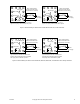
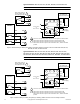
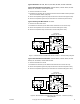
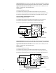
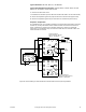
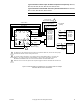

Table Of Contents
- Application
- Features
- Applicable Literature
- SPECIFICATIONS
- ACCESSORIES
- TYPICAL APPLICATIONS (wiring diagrams)
- List of Figures
- Typical Actuators: MP-361, MP-371, MP-381, MP-382, and MP-2113-500.
- Typical Actuators: MP-421, MP-422, MP-423, MP-424, MP-451, MP-452, MP-4553, MP-454, MP-465, MP-483, MP-485, MP-486, MP-495, MP-2130-500, MP-2150-500, MP5-2151-500, MP5-4651, MP5-4751, MP-4851, and MP5-4851.
- Typical Actuators: MP-361, MP-371, MP-381, MP-382, and MP-2113-500.
- Typical TAC Microtherm Controllers: PP-22x Series, TP-2xx Series, TP-3xx Series, TP-4xx Series, and TP-101x Series.
- Typical Cooling TAC Microtherm: TP-1031.
- Typical TAC Microtherm Controllers: PP-22x Series, TP-2xx Series, TP-3xx Series, TP-4xx Series, and TP-101x Series.
- Typical Actuators: MP-465, MP-475, MP-485, MP-486, MP-495, MP-2130-500, MP-2150-500, MP5-2151-500, MP5-4651, MP5-4751, MP-4851, and MP5-4851.
- Typical TAC Microtherm Controllers: PP-22x Series, TP-2xx Series, TP-3xx Series, TP-4xx Series, and TP-101x Series.
- Typical Cooling TAC Microtherm: TP-1031.
- Typical Actuators: MP-465, MP-475, MP-485, MP-486, MP-495, MP-2130-500, MP-2150-500, MP5-2151-500, MP5-4651, MP5-4751, MP-4851, and MP5-4851.
- Typical TAC Microtherm Controllers: PP-22x Series, TP-2xx Series, TP-3xx Series, TP-4xx Series, and TP-101x Series.
- Typical Actuators: MP-367, MP-377, and MP-387.
- Typical TAC Microtherm Controllers: PP-22x Series, TP-2xx Series, TP-3xx Series, TP-4xx Series, and TP-101x Series.
- Sequence of Operation
- Typical TAC Microtherm Controllers: TP-2xx Series, TP-3xx Series, and TP-4xx Series.
- Cycle of Operation
- Typical TAC Microtherm Controllers: TP-2xx Series, TP-3xx Series, and TP-4xx Series.
- Cycle of Operation
- Typical Actuators which require AE-504 purchased separately: MP-361, MP-371, MP-382, and MP-2113-500.
- Typical Actuators which require AE-504 purchased separately: MP-465, MP-475, MP-483, MP-485, MP-486, MP-495, MP-2130-500, MP-2150-500, MP5-4651, MP5-4751, MP-4851, MP5-4851.
- Typical Actuators which require CP-8301-120 purchased separately: MP-421, MP-422, MP-423, MP-424, MP-451, MP-452, MP-454.
- Typical Actuators with CP-8301-120 factory installed and wired: MP-461-600, MP-471-600, MP-481-600, MP-2110-601.
- Typical Actuators which require CP-8301-024 purchased separately: MP-361, MP-371, MP-381, MP-382, MP-2113-500.
- Typical Actuators which require CP-8301-120 purchased separately: MP-465, MP-475, MP-483, MP-485, MP-486, MP495, MP-2130-500, MP-2150-500.
- Typical Actuators which require CP-8301-240 purchased separately: MP5-2151-500, MP5-4651, MP5-4751, MP-4851, MP5-4851.
- Typical Actuators which require CP-8391-913 purchased separately: MP-361, MP-371, MP-381, MP-382, MP-2113-500.
- Typical Actuators which require CP-8391-910 purchased separately: MP-421, MP-422, MP-424, MP-451, MP-452, MP-453, MP-454.
- Typical Actuators which require CP-8391-910 purchased separately: MP-465, MP-475, MP483, MP-485, MP-486, MP-495, MP-2130-500, MP-2150-500.
- Typical Actuators which require CP-8391-716 purchased separately: MP-421, MP-422, MP-423, MP-424, MP-451, MP-452, MP-453, MP-454.
- Typical 120 Vac Actuators which require CP-8391-716 purchased separately: MP-465, MP-475. MP-483, MP-485, MP-486, MP-495, MP-2130-500, MP-2150-500.
- Typical 240 Vac Actuators which require CP-8391-716 purchased separately: MP5-2151-500, MP5-4651, MP5-4751, MP-4851, MP5-4851.
- Typical Actuators: MP-361, MP-371, MP-381, and MP-382.
- Typical Actuators: MP-421, MP-422, MP-423, MP-424, MP-451, MP-452, MP-453, MP-454, MP-461-600, MP-471-600, and MP-481-600.
- Typical Actuators: MP-465, MP-475, MP-483, MP-486, MP-495, MP5-4651, MP5-4751, MP-4851, and MP5-4851.
- Typical Actuator: MP-2113-500.
- Typical Actuator: MP-2110-600.
- Typical Actuators: MP-2130-500, MP-2150-500, MP5-2151-500.
- Typical Actuators: MP-379 and MP-389
- Typical Actuators: MP-470, MP-480, and MP-4701.
- Typical Actuators: MP-367, MP-377, and MP-387.
- List of Figures
- INSTALLATION
- MOUNTING
- WIRING
- ADJUSTMENTS
- CHECKOUT
- GO, NO GO Test
- Slidewire Controller with 24 Vac Actuators
- Slidewire Controller with Line Voltage Actuator
- CP-8301-120, Vdc Interface (TAC System 8000) with Line Voltage Actuators without Internal Transformer
- CP-8301-024, Vdc Interface (TAC System 8000) with 24 Vac Actuators
- CP-8301-120 and CP-8301-240, Vdc Interface (TAC System 8000) with Line Voltage Actuators with Internal Transformer
- CP-8391-xxx Series mAdc Interface
- Positioning the Actuator with the Controller
- GO, NO GO Test
- REPLACEMENT PARTS
- MAINTENANCE
- TROUBLESHOOTING
- REPAIR
- DIMENSIONAL DATA

F-15479-8 © Copyright 2007 TAC All Rights Reserved. 19
Typical Actuators which require CP-8301-120 purchased separately: MP-421,
MP-422, MP-423, MP-424, MP-451, MP-452, MP-454.
Typical Actuators with CP-8301-120 factory installed and wired: MP-461-600,
MP-471-600, MP-481-600, MP-2110-601.
Note: CP-8301-120 is marked CP-8301-620 on factory assemblies.
Figure-16 External Wiring for CP-8301-120, Vdc Interface with Line Voltage
Actuators without Internal Transformer.
4
5
6 7
3
8
2
L1
1
L2X
Green Wire
Case
Ground Screw
CP-8301-120
Solid State
Actuator Drive
(Vdc Input
Signal with
3 Vdc Fixed
Span and
2 to 12 Vdc
Adjustable
Start Point
Blue (-, Common)
Yellow (+, Input Signal)
Red (+20 Vdc,
50 mA Power Supply)
Yellow / Black
Blue / Black
Red / Black
Brown
Brown / White
Brown / Black
Black
White
To AC
Power Supply
1
1 The Blue wire on the CP-8301-120 is grounded. To unground the Blue wire, remove the Green jumper
wire between terminal x and the case ground screw.
2 The actuator rotates clockwise on an increasing Vdc input signal between Blue (-, Common) and
Yellow (+). To rotate the actuator counterclockwise on an increase in input signal, reverse the
Blue/Black and Red/Black leads and reverse the Brown/Black and Brown/White leads.
3 Whenever it is not connected, tape off the red power supply lead from the CP-8301-120 actuator drive.
2
1
Red
Yellow
Blue
+20
OP
COM
Typical
Controllers
Yellow
Blue
AO
COM
SH
Typical DDC
Controllers
3
CP-8102
SLC-8xxx
TP-8xxx
To Controller
(Below)