
User Guide
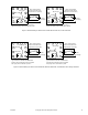
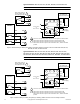
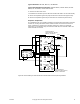
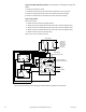
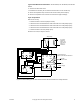
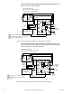
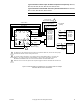

Table Of Contents
- Application
- Features
- Applicable Literature
- SPECIFICATIONS
- ACCESSORIES
- TYPICAL APPLICATIONS (wiring diagrams)
- List of Figures
- Typical Actuators: MP-361, MP-371, MP-381, MP-382, and MP-2113-500.
- Typical Actuators: MP-421, MP-422, MP-423, MP-424, MP-451, MP-452, MP-4553, MP-454, MP-465, MP-483, MP-485, MP-486, MP-495, MP-2130-500, MP-2150-500, MP5-2151-500, MP5-4651, MP5-4751, MP-4851, and MP5-4851.
- Typical Actuators: MP-361, MP-371, MP-381, MP-382, and MP-2113-500.
- Typical TAC Microtherm Controllers: PP-22x Series, TP-2xx Series, TP-3xx Series, TP-4xx Series, and TP-101x Series.
- Typical Cooling TAC Microtherm: TP-1031.
- Typical TAC Microtherm Controllers: PP-22x Series, TP-2xx Series, TP-3xx Series, TP-4xx Series, and TP-101x Series.
- Typical Actuators: MP-465, MP-475, MP-485, MP-486, MP-495, MP-2130-500, MP-2150-500, MP5-2151-500, MP5-4651, MP5-4751, MP-4851, and MP5-4851.
- Typical TAC Microtherm Controllers: PP-22x Series, TP-2xx Series, TP-3xx Series, TP-4xx Series, and TP-101x Series.
- Typical Cooling TAC Microtherm: TP-1031.
- Typical Actuators: MP-465, MP-475, MP-485, MP-486, MP-495, MP-2130-500, MP-2150-500, MP5-2151-500, MP5-4651, MP5-4751, MP-4851, and MP5-4851.
- Typical TAC Microtherm Controllers: PP-22x Series, TP-2xx Series, TP-3xx Series, TP-4xx Series, and TP-101x Series.
- Typical Actuators: MP-367, MP-377, and MP-387.
- Typical TAC Microtherm Controllers: PP-22x Series, TP-2xx Series, TP-3xx Series, TP-4xx Series, and TP-101x Series.
- Sequence of Operation
- Typical TAC Microtherm Controllers: TP-2xx Series, TP-3xx Series, and TP-4xx Series.
- Cycle of Operation
- Typical TAC Microtherm Controllers: TP-2xx Series, TP-3xx Series, and TP-4xx Series.
- Cycle of Operation
- Typical Actuators which require AE-504 purchased separately: MP-361, MP-371, MP-382, and MP-2113-500.
- Typical Actuators which require AE-504 purchased separately: MP-465, MP-475, MP-483, MP-485, MP-486, MP-495, MP-2130-500, MP-2150-500, MP5-4651, MP5-4751, MP-4851, MP5-4851.
- Typical Actuators which require CP-8301-120 purchased separately: MP-421, MP-422, MP-423, MP-424, MP-451, MP-452, MP-454.
- Typical Actuators with CP-8301-120 factory installed and wired: MP-461-600, MP-471-600, MP-481-600, MP-2110-601.
- Typical Actuators which require CP-8301-024 purchased separately: MP-361, MP-371, MP-381, MP-382, MP-2113-500.
- Typical Actuators which require CP-8301-120 purchased separately: MP-465, MP-475, MP-483, MP-485, MP-486, MP495, MP-2130-500, MP-2150-500.
- Typical Actuators which require CP-8301-240 purchased separately: MP5-2151-500, MP5-4651, MP5-4751, MP-4851, MP5-4851.
- Typical Actuators which require CP-8391-913 purchased separately: MP-361, MP-371, MP-381, MP-382, MP-2113-500.
- Typical Actuators which require CP-8391-910 purchased separately: MP-421, MP-422, MP-424, MP-451, MP-452, MP-453, MP-454.
- Typical Actuators which require CP-8391-910 purchased separately: MP-465, MP-475, MP483, MP-485, MP-486, MP-495, MP-2130-500, MP-2150-500.
- Typical Actuators which require CP-8391-716 purchased separately: MP-421, MP-422, MP-423, MP-424, MP-451, MP-452, MP-453, MP-454.
- Typical 120 Vac Actuators which require CP-8391-716 purchased separately: MP-465, MP-475. MP-483, MP-485, MP-486, MP-495, MP-2130-500, MP-2150-500.
- Typical 240 Vac Actuators which require CP-8391-716 purchased separately: MP5-2151-500, MP5-4651, MP5-4751, MP-4851, MP5-4851.
- Typical Actuators: MP-361, MP-371, MP-381, and MP-382.
- Typical Actuators: MP-421, MP-422, MP-423, MP-424, MP-451, MP-452, MP-453, MP-454, MP-461-600, MP-471-600, and MP-481-600.
- Typical Actuators: MP-465, MP-475, MP-483, MP-486, MP-495, MP5-4651, MP5-4751, MP-4851, and MP5-4851.
- Typical Actuator: MP-2113-500.
- Typical Actuator: MP-2110-600.
- Typical Actuators: MP-2130-500, MP-2150-500, MP5-2151-500.
- Typical Actuators: MP-379 and MP-389
- Typical Actuators: MP-470, MP-480, and MP-4701.
- Typical Actuators: MP-367, MP-377, and MP-387.
- List of Figures
- INSTALLATION
- MOUNTING
- WIRING
- ADJUSTMENTS
- CHECKOUT
- GO, NO GO Test
- Slidewire Controller with 24 Vac Actuators
- Slidewire Controller with Line Voltage Actuator
- CP-8301-120, Vdc Interface (TAC System 8000) with Line Voltage Actuators without Internal Transformer
- CP-8301-024, Vdc Interface (TAC System 8000) with 24 Vac Actuators
- CP-8301-120 and CP-8301-240, Vdc Interface (TAC System 8000) with Line Voltage Actuators with Internal Transformer
- CP-8391-xxx Series mAdc Interface
- Positioning the Actuator with the Controller
- GO, NO GO Test
- REPLACEMENT PARTS
- MAINTENANCE
- TROUBLESHOOTING
- REPAIR
- DIMENSIONAL DATA

F-15479-8 © Copyright 2007 TAC All Rights Reserved. 13
Typical Actuators: MP-361, MP-371, MP-381, MP-382, and MP-2113-500.
Typical TAC Microtherm Controllers: PP-22x Series, TP-2xx Series, TP-3xx
Series, TP-4xx Series, and TP-101x Series.
C =Common of Switch to R and B.
1 =Feedback from actuator (24 Vac with actuator full Counterclockwise rotation (CCW) to
12 Vac at Clockwise rotation (CW) end).
R =Closes on temperature (pressure) drop and drives the actuator CCW (opens valve).
B =Closes on temperature (pressure) rise and drives the actuator CW (closes valve).
Typical Cooling TAC Microtherm: TP-1031.
C =Common of switch to R and B.
1 =Feedback from Actuator (24 Vac with actuator full CCW to 12 Vac at CW end).
R =Closes on temperature rise and drives the actuator CCW (opens valve).
B =Closes on temperature drop and drives the actuator CW (closes valve).
Figure-7 TAC Microtherm Controller with 24 Vac Actuators – Standard Wiring Diagram.
Typical TAC Microtherm Controllers: PP-22x Series, TP-2xx Series, TP-3xx
Series, TP-4xx Series, and TP-101x Series.
C =Common of Switch to R and B.
1 =Feedback from Actuator (12 Vac with Actuator full CCW to 24 Vac at CW end).
R =Closes on temperature (pressure) drop and drives the actuator CW (closes valve).
B =Closes on temperature (pressure) rise and drives the actuator CCW (opens valve).
Figure-8 TAC Microtherm Controller with 24 Vac Actuators – Reversed (Cooling)
Wiring Diagram.
4 5
6 7
3
8
2
H
1
G
X
Green Wires
To 24 Vac
Power Supply
Case
Ground Screw
C
2
R
1
B
Case
Ground
Screw
Add
Jumper
Add Resistor
(Supplied With Actuator)
100
4
5
6 7
3
8
2
H
1
GX
Green Wires
To 24 Vac
Power Supply
Case
Ground Screw
C
2
R
1
B
Case
Ground
Screw
Add
Jumper
Add Resistor
(Supplied With Actuator)
100