
Submittal Sheet
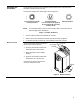


Start-Up/
Commissioning,
Continued
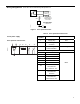
5. Check the Auxiliary Switch B:
a. Set the DMM dial to ohms (resistance) or continuity check.
b. Connect wires S4 and S6 to the DMM.
The DMM should indicate an open circuit or no resistance.
c. Apply a control signal (24 Vac) to wires 1 (red) and 6 (violet).
The DMM should indicate contact closure as the actuator shaft coupling
reaches the setting of switch B.
d. Stop applying a control signal to wires 1 (red) and 6 (violet).
e. Connect wires S4 and S5 to the DMM.
The DMM should indicate an open circuit or no resistance.
f. Apply a control signal (24 Vac) to wires 1 (red) and 7 (orange).
The DMM should indicate contact closure as the actuator shaft coupling
reaches the setting of switch B.
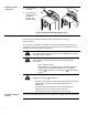
Service
WARNING:
Do not open the actuator.
If the actuator is inoperative, replace the unit.
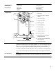
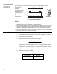
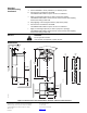
Dimensions
90
2-3/4
(70)
5/32
(4)
13/16
(21)
3-7/16
(87)
5-7/16
(137)
15/16
(94)
7/16
(11)
min. 4 inch
100 mm
2-3/8
(60)
1/32
(0.8)
EA0530R3
min. 1/4 inch
6 mm
min. 8 inch
200 mm
min. 3/8 inch
10 mm
min. 1 inch
25 mm
min. 2-3/8 inch
60 mm
6-5/8
(168)
7-1/16
(180)
EA0531R2
1/2
(12)
25/32
(20)
Figure 8. Dimensions of the TAC DuraDrive Actuator and Anti-rotation Bracket.
Copyright 2008, TAC
All brand names, trademarks and registered trademarks
are the property of their respective owners. Information
contained within this document is subject to change
without notice.
F-27213-2
TAC
1354 Clifford Avenue
P.O. Box 2940
Loves Park, IL 61132-2940
www.tac.com