
Submittal Sheet
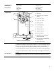
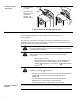


Mechanical range
adjustment
1. Loosen the stop
set screw.
2. Move the screw
along the track to
the desired
position, and
fasten it in place.
45
90
90
EA0535R2
4 mm
45¡
90¡
90¡
EA0536R2
<
90¡
Figure 6. Moving the Mechanical Range Stop.
Wiring
All wiring must conform to NEC and local codes and regulations.
Use earth ground isolating step-down Class 2 transformers. Do not use
autotransformers.
The sum of the VA ratings of all actuators and all other components powered by one
transformer must not exceed the rating of the transformer. It is recommended that one
transformer power no more than 10 actuators.
CAUTION:
Do not wire different types of actuators (such as MS/MF41-6153 Series)
in parallel with these models.
WARNING:
All six outputs of the dual auxiliary switch (A and B) must only be
connected to:
Class 2 voltage (UL/cUL),
Separated Extra-Low Voltage (SELV) or Protective Extra Low
Voltage (PELV) (according to HD384-4-41) for installations
requiring
conformance. You must use a certified plenum
actuator.
WARNING:
Installations requiring
Conformance:
• All wiring for CE certified actuators must only be separated extra low
voltage (SELV) or protective extra low voltage (PELV) per
HD384-4-41.
• Use safety-isolating transformers (Class III transformer) per
EN61558. They must be rated for 100% duty cycle.
• Overcurrent protection for supply lines is maximum 10A.
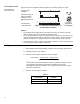
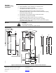
Direction of damper
rotation
To reverse the direction of rotation, wires 6 (violet) and 7 (orange) can be interchanged.
1
2
6