
Submittal Sheet
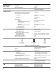
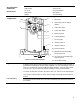
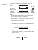
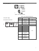

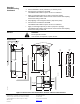

Figure 3 shows the adjustable switching values for the auxiliary switches A and B.
Dual Auxiliary Switch
MF41-6043-502
MF41-6083-502
Actuator Scale:
clockwise
Adjustment range for
Switches A and B
Setting interval: 5°
Switching hysteresis:
2°
Actuator Scale:
counterclockwise
AB
-2,5 0 10 20 30 70 80 90 92,5
0 10 20 30 70 80
EA0640R1
92,5 90 80 70
60
20 10
-2,5
90
0
Figure 3. Adjustable Switching Values for
the dual auxiliary Switches.
80 70 60
2010
AUX SWITCH
ADJUSTMENT
A ˚
B
50
EA0636R1
NOTES:
• The auxiliary switch setting shafts rotate with the actuator. The scale is valid only
when the actuator is in the “0” position on clockwise motion.
• For the counterclockwise rotation, the adjustment lever has to move from 90° to 0° by
using the manual override and then adjust the auxiliary switches. After the auxiliary
switches are adjusted, the adjustment lever has to move back to the 90° position.
• Use the long arm of the X to point to the position of switch A. Use the narrower tab on
the red ring to point to the position of switch B.
Sizing
The type of actuator required depends on several factors.
1. Obtain damper torque ratings (ft-lb/ft
2
or Nm/m
2
) from the damper manufacturer.
2. Determine the area of the damper.
3. Calculate the total torque required to move the damper:
Total Torque =
SF
ea Damper Aring Torque Rat
1
×
1
Safety Factor: When determining the torque of an actuator required, a safety
factor should be included for unaccountable variables such as slight
misalignments, aging of the damper, etc. A suggested safety factor is 0.80 (or
80% of the rated torque).
4. Select the actuator type from Table 2.
Table 2.
Total Torque Actuator
<35 lb-in (4 Nm) MF41-6043 Series
<70 lb-in (8 Nm) MF41-6083 Series
4