
Submittal Sheet


Specifications,
Continued
Miscellaneous
Pre-cabled connection 18 AWG
Cable length 3 feet (0.9 m)
Life cycle Five-year warranty
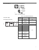
Dimensions See Figure 8
Weight 1.06 lb (0.48 kg)
Actuator
Components
80 70 60
2010
Aux Switch
Adjustment
A B
50
90
90
45
EA0642R3
1
2
12
10
8,9
11
6
13
34
5
7
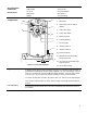
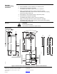
Figure 2. Parts of the Actuator.
Legend
1. Base plate
2. Positioning scale for angle of
rotation
3. Connection cables
4. Connection cables
5. Manual override
6. Coupling bushing
7. 1/2-inch guide
8. Auxiliary switch A
9. Auxiliary switch B
10. Position indicator
11. Adjustment lever with locking
screw (4 mm hex)
12. Set screw for mechanical range
stop (3 mm hex)
13. Anti-rotation bracket
Operation
A floating control signal controls the damper actuator. The actuator’s angle of rotation is
proportional to the length of time the signal is applied. A 24 Vac control signal to wires 1
and 6 (G-Y1) causes the actuator coupling to rotate clockwise. A 24 Vac control signal
to wires 1 and 7 (G-Y2) causes the actuator coupling to rotate counterclockwise.
To reverse the direction of rotation, the wires 6 and 7 (Y1 and Y2) can be interchanged.
In the event of a power failure or with no control voltage, the damper actuator holds its
position.
Life expectancy
An improperly tuned loop will cause excessive repositioning that will shorten the life of
the actuator.
3