
Install Instructions
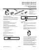
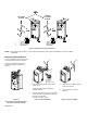
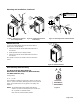
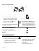
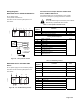
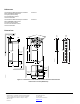
Table Of Contents

Counterclockwise Damper Rotation of MF41-6043
Series and MF41-6083 Series
If the damper blades turn counterclockwise to open (CCW),
reverse the 6 (violet) and 7 (orange) wires at the controller.
Wiring Diagrams
MF41-6043 Series and MF41-6083 Series
24 Vac power supply
Three-position control 24 Vac
Each wire has the standard symbol printed on it.
See Table 1.
CAUTION:
Do not wire different types of actuators (such as MF41-
6153 Series) in parallel with these models.
Table 1. Three-position Control 24 Vac.
Standard
Symbol
Function
Color
1 Supply (SP) Red
6 Control signal clockwise Violet
7 Control signal counterclockwise Orange
M
A
B
1000
P1
P3P2 S1
S4
S2 S3 S5 S6
1
6
7
EA0282R1
Factory-installed Options
S1
Switch A Common
S2
Switch A NC
S3
Switch A NO
S4
Switch B Common
S5
Switch B NC
S6
Switch B NO
P1
Feedback Potentiometer
0 to 100% P1 - P2
P2
Feedback Potentiometer Common
P3
Feedback Potentiometer
100 to 0% P3 - P2
Black
EA0635R2
24
Vac
EARTH GROUND
ISOLATING CLASS 2
TRANSFORMER FOR
24 Vac POWER
: SAFETY ISOLATING
TRANSFORMER
PER EN 60742
120 Vac
7 (ORANGE)
6 (VIOLET)
1 (RED)
NEUT
Figure 15. Three-position Control.
MS41-6043 Series and MS41-6083
Series
24 Vac power supply 0 to 10V modulating control
Each wire has the standard symbol printed on it.
See Table 2.
M
A
B
S1
S4
S2 S3 S5 S6
1
8
2
9
EA0284R1
Figure 16. 0 to 10V Modulating Control.
Table 2. Modulating Control.
Standard
Symbol
Function Color
1 Supply (SP) Red
2 Neutral (SN) Black
8 0 to 10V input signal Gray
9 Output for 0 to 10 Vdc position indication Pink
Factory-installed options
S1 Switch A Common
S2 Switch A NC
S3 Switch A NO
S4 Switch B Common
S5 Switch B NC
S6 Switch B NO
Black
Page 5 of 6