
Install Instructions
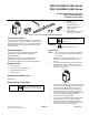
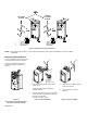
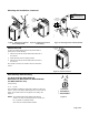
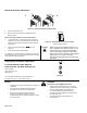
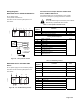
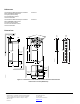
Table Of Contents

Mechanical Range Adjustment
Page 4 of 6
45
90
90
EA0535R2
4 mm
45¡
90¡
90¡
<
90¡
EA0536R2
Figure 12. Moving the Mechanical Range Stop.
0
self adapt
EA0621R1
Figure 13. Self-adapt Switch in the On Position.
Factory setting 0 (OFF)
1. Loosen the stop set screw.
2. Move it along the track to the desired position, and
fasten it in place.
Mechanical range limitation and self–adapt feature.
1. To use the entire 0 to 10V input signal to control the
adjusted range, raise the tab located on the lower left-
hand side of the actuator and locate the DIP switches.
See Figure 3.
2. Set the self-adapt DIP switch to
(ON). See
Figure 13.
3. Close the tab over the DIP switches.
For example, if you set the locking screw at 70° and turn the
self-adapt switch ON, a 5V input signal will drive the damper
to 35° (50% of its adjusted range).
CAUTION:
When turning the self-adaptive feature on, or
after a software reset with the feature on, the
actuator will enter a five-minute calibration
cycle as the actuator adjusts to the rotation
limits of the system. A software reset happens
after power on, or may be caused by
electrostatic discharge (ESD) at levels of 2kV
and above.
Slope (Span) and Offset Adjustment
For MS41-6083-520, MS41-6083-522,
MS41-6043-520, and MS41-6043-522 only.
Factory setting:
Slope (span) ΔU ≈10
Offset Uo = 0
Use a flat-blade screwdriver to make adjustments.
The long arm of the "
†" points to the setting.
EA0633R1
U
Uo
U
Ys
V
30
2
16
10
24
Uo
2
4
0
1
3
5
Figure 14.
Wiring
• All wiring must conform to NEC and local codes and
regulations.
• Use earth ground isolating step-down Class 2
transformers. Do not use auto transformers.
• Determine the supply transformer rating by
summing total VA of all actuators used. It is
recommended that one transformer power no more
than 10 actuators.
WARNING:
Installations requiring Conformance
• All wiring for CE rated actuators must only be
separated extra low voltage (SELV) or protective
extra low voltage (PELV) per HD384-4-41.
• Use safety-isolating transformers (Class III
transformer) per EN 61558. They must be rated
for 100% duty cycle.
• Overcurrent protection for supply lines is
maximum 10A.
2 1