
Install Instructions
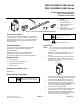
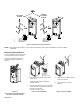
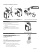
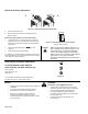
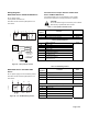
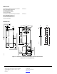
Table Of Contents

Mounting and Installation, Continued
45
90
90
EA0532R2
2
1
3
45
90
90
EA0533R3
4 mm
b
5
4
60-90 lb-in
(7-10 Nm)
Torque
EA0786R4
1/2
1/2
d
c
d
CENTER THE
MOUNTING BRACKET
IN THE SLOT
CAUTION:
THESE HOLES FOR USE WITH
ACCESSORY KITS ONLY. DO NOT
USE IN THE INSTALLATION OF
DIRECT-COUPLED APPLICATIONS
∅4 mm
5/32 in.
Figure 7. Mounting the Actuator
to the Damper Shaft.
Figure 8. Installing the Position
Indicator (b).
Figure 9. Attaching the Anti-rotation Bracket.
Manual Override
To move the damper blades and lock the position with no
power present, do the following:
1. Slide the red manual override knob toward the back of
the actuator.
2. Make adjustments to the damper position.
3. Slide the red manual override knob toward the front of
the actuator.
Once power is restored, the actuator returns to automated
control.
45
90
90
PL0013R2
MANUAL
ADJUSTMENT
LEVER
AUTO
2
1
3
Figure 10. Manual Override.
Dual Auxiliary Switch Setting
For MF41-6043-502, MS41-6043-502,
MS41-6043-522, MF41-6083-502, MS41-6083-502,
and MS41-6083-522, only.
Factory setting:
A = 5° B = 85°
Use a flat-blade screwdriver to adjust the A switch. The long arm
of the "
†" points to the setting. Manually turn the red ring of the B
switch. The narrower tab on the ring points to the setting. See
Figure 10.
NOTE: The auxiliary switch setting shafts rotate with the
actuator. The scale is valid only when the actuator is in
the "0" position on clockwise motion.
Invert scale for counterclockwise rotation.
80 70 60
2010
AUX SWITCH
ADJUSTMENT
A ˚
B
50
EA0636R1
Figure 11.
Page 3 of 6