
Install Instructions
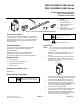
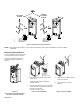
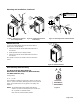
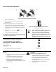
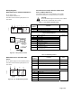
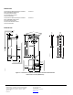
Table Of Contents

1
2
3
2’
3’
only for:
MS41-6043 SERIES
MS41-6083 SERIES
MODULATING
"0"
1
.8
.6
.4
.2
0
0
self adapt
0
0
self adapt
CLOCKWISE
TO OPEN
COUNTER
CLOCKWISE
TO OPEN
0
PL0047R1
self adapt
self adapt
only for:
MS41-6043 SERIES
MS41-6083 SERIES
MODULATING
1
.8
.6
.4
.2
0
Figure 3. Setting the Direction of Rotation.
NOTE: For DIP switch setting options, see the General Instructions F-27213-1 (MF41-6043/608) and F-27214-1 (MS41-
6043/6083).
Mounting and Installation
The TAC DuraDrive actuator comes with
a factory installed 1/2-inch shaft guide.
If shaft size is 5/8-inch, skip Figure 5
and proceed with the instructions in
Figure 6.
EA0999R1
45
90
90
PL0028R2
f
Mounting on
3/8-inch
8...10 mm shafts
~
~
1. Remove factory installed 1/2-inch guide.
See Figure 4.
A 3/8-inch shaft adapter is provided in
actuator package.
2. Hold the shaft insert so that the raised tabs
are inserted last when placing the insert into
the back of the actuator.
Proceed to Figure 6, step 2.
45
90
90
EA0001R2
1. Remove factory installed 1/2-inch
guide. See Figure 4.
2. Mount actuator to shaft per
Figure 6.
Figure 4.
Removing 1/2-inch Shaft Guide for
3/8-inch Ø or 5/8-inch Ø Shaft.
Figure 5. 3/8-inch Ø Shaft. Figure 6. 5/8-inch Ø Shaft.
Page 2 of 6