
User Guide


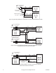

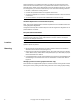


Table Of Contents
- Application
- Features
- . Two position models controlled by SPST controller
- . Floating models controlled by SPDT floating controllers
- . Proportional models controlled by 0-3 Vdc, 6-9 Vdc, 0-10 Vdc, 0-20 mAdc, 2-10 Vdc, or 4-20 mAdc. Control function direct/reverse action is jumper selectable
- . 105 lb force (467 newton) with 1/2" (13 mm) nominal linear stroke
- . 24 Vac, 120 Vac, and 230 Vac models
- . Rugged polymer housings rated for up to NEMA 2/IP54
- . Overload protection throughout stroke
- . Automatically sets input span to match valve travel
- . Compact size to allow installation in limited space
- . Manual override to allow positioning of valve and preload
- . Spring return operation
- . Direct mount to valves without separate linkage
- . Polymer housing rated for plenum use
- . Five year warranty
- Applicable Literature
- SPECIFICATIONS
- TYPICAL TWO POSITION CONTROL (wiring diagrams)
- Figure-1 Typical Wiring Diagrams for Two Position Actuators
- TYPICAL FLOATING CONTROL (wiring diagrams)
- TYPICAL PROPORTIONAL CONTROL (wiring diagrams)
- INSTALLATION
- Figure-8 Wire Diagram Notes Guide
- Inspection
- Requirements
- Precautions
- Location
- Mounting
- Changing Control Function (proportional units only)
- Installation: Mx51-710x Series Actuator to 1/2" to 2" VB-7xxx Series Valve Bodies, 2-Way Stem-Up Closed and 3-Way Mixing or Diverting Applications
- A. Preload the valve to insure proper close-off according to the numbered steps in Figure-10 and the text below. (Remove power before proceeding.)
- 1. Locate the steel jam nut that came packaged with the actuator. (Do not re-use the brass jam nut present on an existing valve.)
- 2. Screw the nut onto the valve stem all the way as far as it will go (you may need to use a TOOL-20-1 or a 5/16” open-end wrench). At least 1/2” of the valve stem should extend above the nut.
- 3. Thread the stem extension onto the valve stem, making contact with the jam nut. Raise the valve stem to the full up position.
- 4. Orient the actuator mounting bracket on the valve and tighten the hex mounting nut securely against the bracket using TOOL-37.
- 5. Insert the crank provided in the actuator cover. Wind the crank two turns counterclockwise. Press in the turn crank 1/8 turn counterclockwise to lock in position.
- 6. Rotate the stem extension until the through holes in the stem extension and rack line up. Insert connecting pin to secure stem extension and tighten jam nut against stem extension using TOOL-20-1 or a 5I16” open end wrench.
- B. Apply power to the actuator and check the system operation for heating or cooling output in response to the control signal.
- Installation: Mx51-710x Series Actuator to 1/2" to 2" VB-7xxx Series Valve Bodies, 2-Way Stem-Up Open
- A. Preload the valve to insure proper close-off according to the numbered steps to 10 and the text below. (Remove power before proceeding.)
- 1. Locate the steel jam nut that came packaged with the actuator. (Do not re-use the brass jam nut present on an existing valve.)
- 2. Screw the nut onto the valve stem all the way as far as it will go (you may need to use a TOOL-20-1 or a 5/16” open-end wrench). At least 1/2” of the valve stem should extend above the nut.
- 3. Thread the stem extension onto the valve stem, making contact with the jam nut. Push the valve stem to the full down position.
- 4. Orient the actuator mounting bracket on the valve and tighten the hex mounting nut securely against the bracket using TOOL-37.
- 5. Insert the crank provided in the actuator cover. Wind the crank counterclockwise until the actuator fully extends, then unwind 2 turns and press in and turn crank 1/8 turn counterclockwise to lock in position.
- 6. Rotate the stem extension until the through holes in the stem extension and rack lineup. Insert connecting pin to secure stem extension and tighten jam nut against stem extension using TOOL-20-1 or a 5I16” open end wrench.
- B. Apply power to the actuator and check the system operation for heating or cooling output in response to the control signal.
- Valve Mounting
- 1. Following general piping practices is recommended.
- 2. Apply pipe sealant sparingly to all but the last two threads of a properly threaded, reamed, and cleaned pipe. Make sure the ...
- 3. Start the joint hand-threading the pipe into the valve. If the thread alignment feels normal, continue to turn the pipe by hand as far as it will go.
- 4. Use a pipe wrench to fully tighten the pipe to the valve.
- 5. Insulate only the valve body and associated piping, not the actuator.
- 6. In chilled or cold water systems where the environment is humid, use a drip pan under the valve to catch condensate.
- Figure-11 Acceptable Mounting Orientations for Non-Steam Applications
- Figure-12 Acceptable Mounting Orientation for Steam Applications
- 1. Following general piping practices is recommended.
- MANUAL OVERRIDE OPERATION
- Figure-13 Unacceptable Mounting Orientation
- 1. Disconnect power from the actuator. The actuator will fully retract.
- 2. Without pushing down on the crank, crank the manual override counterclockwise until the actuator extends to the desired position. Push in until the mechanism locks in position. (The manual override lock will release the next time power is applied.)
- 3. If you desire to reposition the actuator manually from a locked position, turn the crank 1/8 turn counterclockwise and pull out to release. Adjust position as desired.
- Wiring Requirements
- Table-2 Power Wiring
- CHECKOUT
- THEORY OF OPERATION
- MAINTENANCE
- FIELD REPAIR

F-27169-5 © Copyright 2007 TAC All Rights Reserved. 5
TYPICAL PROPORTIONAL CONTROL (wiring diagrams)
Figure-6 illustrates typical wiring diagrams for spring return proportional MS51-7103
actuators. See Table-1 for model selection. See 8 for wiring diagrams notes guide.
Caution: This product contains a half-wave rectifier power supply and must not be
powered off transformers used to power other devices utilizing non-isolated full-wave
rectifier power supplies. Refer to EN-206, Guidelines for Powering Multiple Devices from a
Common Transformer, F-26363 for detailed information.
MF51-7103-xxx
Red
Black
Common
Hot (+DC)
1
Line
Volts
Controller
Blue
2
Yellow/Black
Hot
Common
3
Extend
Retract
24 Vac Transformer
or 20-30 Vdc
(-)
(+)
Feedback Signal
2 to 10 Vdc
Violet
AO
4 8
Figure-4 Triac Sink
1
Line
Volts
24 Vac Transformer
or 20-30 Vdc
MF51-7103-xxx
Red
Black
Common
Hot (+DC)
1
Line
Volts
Controller
Blue
Yellow/Black
Hot
Common
Extend
Retract
24 Vac Transformer
or 20-30 Vdc
(-)
(+)
Feedback Signal
2 to 10 Vdc
Violet
AO
2
3
4 8
Figure-5 Triac Sink With Separate Transformers
Figure-6 Typical Wiring Diagrams for Proportional Control 24 Vac Basic Models
Vdc
Feedback Signal
Red
Blk
Com
Hot (+DC)
Line
Volts
(-)
(+)
(-)
(+)
Vdc or mAdc
Control Signal
Yel/Blk
AI
1
MS51-7103-xxx
Vdc Proportional Control
Violet AO
24 Vac Transformer
or 20-30 Vdc
To Additional
2-10 Vdc
Actuators
Hot (+DC)
Red
Blk
Com
Line
Volts
(-)
(+)
Control Signal
4 to 20 mAdc
Yel/Blk
Violet
(-)
(+)
Feedback Signal
2 to 10 Vdc
4
AI
AO
MS51-7103-x00
5
1
4 to 20 mAdc with 2-10 Vdc Actuators
500 Ω
24 Vac Transformer
or 20- 30 Vdc
2
2
4
2
4
6 8
8