
User Guide


F-26742-2 © Copyright 2006 TAC All Rights Reserved. 5
INSTALLATION
Inspection Inspect the package for damage. If damaged, notify the appropriate carrier immediately.
If undamaged, open the package and inspect the device for obvious damage. Return
damaged products.
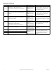
Requirements • Job wiring diagrams
• Tools (not provided)
– Socket wrench 1/2 inch, used for universal mounting clamp nuts
– Open-end wrench 10 mm, used for installing AM-676 universal shaft extension
– Slotted screwdriver, used for installing anti-rotation brackets
– Allen wrench 3/16", used for manual override
• Appropriate accessories
– Water tight 1/2 inch conduit seals TAC part number TF-711-02 or T&B #5332
(straight, TAC part number TF-713-02 or T&B #5352 (90°), or equivalent.
– Water tight 1/2 inch flexible conduit (e.,g. Anaconda: Sealtight) or 20 mm flexible
water tight conduit when using AM-756 metric conduit adapter with appropriate
metric water tight seals.
– Water tight 1/2 inch flexible conduit (Anaconda: Sealtight) or 20 mm flexible water
tight conduit when using AM-756 metric conduit adapter
– Two #8 1/2 inch (13 mm) sheet metal screws for mounting anti-rotation bracket
(optional)
• Training: Installer must be a qualified, experienced technician
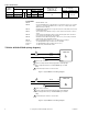
Figure-3 Typical MA40-7173 Wiring Diagram.
MA40-7173
Black
Black/Blue
24H
24G
24 Vac
GRDGreen/Yellow
1
2
1 SPST or Triac Controller. Multiple MA40-7173 actuators may be powered
by a single 24 Vac transofrmer.
2 Unused conduit port must remain plugged with a water tight pipe plug as
shipped from factory to maintain NEMA Type 4 or IP56 rating.
3 Ground wire may be Green on some models.
3