
User Guide


12 © Copyright 2006 TAC All Rights Reserved. F-26742-2
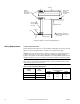
Wiring Requirements Control and Power Leads
Remove blue plastic thread protectors before installing conduit fittings. See Figure-1 through
Figure-1 for typical wiring applications and Table-3 for maximum wire lengths.
Caution:
The 24 Vac model contains a half-wave rectifier power supply and must not be
powered by transformers used to power other devices utilizing non-isolated full-wave
rectifier power supplies. Refer to
EN-206 Guidelines for Powering Multiple Full-Wave and
Half-Wave Rectifier Devices from a Common Transformer
, F-26363, for further information.
Note:
Class 2 control and power lead wiring must be routed separately from line voltage
wiring and any other non-class 2 circuits.
Table-3 Control and Power Wiring Data.
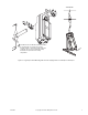
Figure-8 Installation of Universal Shaft Extension.
Actuator
AM-753
Universal
Mounting Clamp
Assemblies
Duct
V-clamp
Mounting Surface
Damper Shaft
AM-676
Universal Shaft
Extension
1
1 The AM-676 extends the
damper shaft approximately
9" (229 mm).
Anti-rotation
Bracket
(included with
actuator)
Actuator
Voltage
Part
Number
Maximum Wire Run in ft. (m)
(5% Voltage Drop)
14 AWG 16 AWG 18 AWG
24 Vac MA40-7173
1165
(355)
733
(223)
461
(141)
120 Vac MA40-7170
240 Vac MA40-7171