
User Guide

Schneider Electric 1354 Cliffo rd Ave. Loves Park, IL 61111 1-888 - 44 4 -1311 w ww.schneider-electric.co m / buildings
F-27599-4 March 2011 co
© 2011 Schneider Electric. All rights reserved.
11
Globe Valve Actuators & Assemblies
Forta
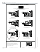
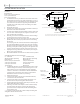
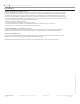
ACTUATOR INSTALLATION
U-Bolt Forta mounted on VB-7000 valve
mounting boss
actuator linkage slot
Bonnet adapter
Jam nut
Stem adapter
Red Manual Override Lever
Shown in Auto Position
Bottom of the
Top of the
Screw-Mount Forta
Actuator Linkage Slot
Stem Adaptor
Actuator Stem Height
Valve Nut
Top of the Actuator Yoke Slot
Red Manual Override Lever
Shown in Auto Position
Note: Clockwise and Counter-Clockwise directional orientation in the installation instruction is
described from the underside of the actuator, not from the view above.
Stem Nut
Short, Threaded Forta Valves Installation on a 1/2” - 2” VB-7000: Valve
Installation
Required Tools:
M-370 1 5/8” open end wrench
7/16” open end wrench
5/16” open end wrench
Con rm that the factory set dimension from the bottom of the 1.
actuator linkage slot to the top of the mounting boss is 7/8”. If
the actuator is not set at this dimension please adjust the actua-
tor to obtain this 7/8” dimension by placing the Red Manual
Override Lever in the down position and rotating it to obtain
required position.
Pull up the valve stem.2.
Screw the stem adapter jam nut (provided with the actuator) to 3.
the bottom of the valve stem threads.
Screw the stem adapter (provided with the actuator) all the way 4.
on to the valve stem to the jam nut, using the 5/16” and 7/16”
open end wrenches and tighten.
Slide the groove of the stem adapter in to the actuator linkage 5.
slot and position the actuator on to the valve.
Engage the large valve nut several turns on to the actuator yoke 6.
by hand (the valve stem may be pushed into the valve during
this process).
To create plug and seat clearance before nal assembly tighten-
ing, lower the Red Manual Override Lever and rotate clockwise
ve turns (looking from the bottom of the actuator). If you skip
this step, you may have trouble getting the valve tight onto the
actuator and risk damaging internal components of the valve.
Fully tighten the large valve nut to the actuator yoke using the 7.
M-370 1 5/8” open end wrench.
Raise the Red Manual Override Lever to allow actuator operation.8.
U-Bolt Mount (Tall) Forta: Valve Installation
½” – 2” VB-7000
AV-821 (Purchase Separately)
Required Tools:
M-370 1 5/8” open end wrench
7/16” open end wrench
5/16” open end wrench
13 mm wrench
Con rm that the factory set dimension from the bottom of the 1.
actuator linkage slot to the top of the mounting boss is 2 1/4”.
If the actuator is not set at this dimension please adjust the
actuator to obtain this 2 1/4” dimension with the Red Manual
Override Lever in the down position turn as required. Raise
Red Manual Override Lever after re-positioning.
Pull up the valve stem.2.
Screw the stem adapter jam nut, provided with the AV-82x, 3.
1/2” down the valve stem threads.
Screw the stem adapter, provided with the AV-82x kit, on to 4.
the valve stem to the jam nut, tighten with wrenches.
Install the AV-82x bonnet adapter all the way on the valve, and 5.
tighten with appropriate wrenches.
Slide the goove of the stem adapter in to the actuator linkage 6.
slot and position the actuator onto the valve aligning the
grove of the bonnet adapter with the U-Bolt mounting holes
in the actuator yoke.
7. Install the U clamp and the two 13mm U clamp mounting nuts
and tighten with the 13mm wrench.
2 ½” – 6” VB-8000/9313
AV-822 (Purchase Separately)
Required Tools:
3/4” open end wrench
5/8” open end wrench
13 mm wrench
Pipe wrench