
User Guide

Schneider Electric 1354 Cliffo rd Ave. Loves Park, IL 61111 1-888 - 44 4 -1311 w ww.schneider-electric.co m / buildings
F-27599-4 March 2011 co
© 2011 Schneider Electric. All rights reserved.
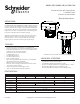
Globe Valve Actuators & Assemblies
Forta
10
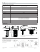
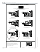
With the actuator powered and being controlled by the input signal the optional auxiliary switches only transfer contacts as
follows, driving from full retract to full extend the auxiliary contacts transfer when the actuator is about 95% of full extend travel.
When the actuator drives from full extend to full retract the contacts will transfer when the actuator is about 95% of full retract travel.
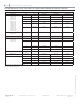
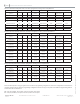
Optional Auxiliary Switch Function (S2)
Example A Example B Example C Example D
Auxliary Switches
2- SPDT
Program Switch 1 OFF
Powered
Retracted
Program Switch 1 ON
Powered
Extended
Program Switch 1 OFF
Powered
Retracted
Program Switch 1 ON
Powered
Extended
Closed Open Closed Open Closed Open Closed Open
KC1-K1 X X X X
KC1-K2 X X X X
KC2-K3 X X X X
KC2-K4 X X X X
Floating Control or
Proportional Control
Program switches 1 o , 7 o Program switches 1 on, 7 on Program switches 1 o , 7 on Program switches 1 on, 7 o
High Input Signal or
D1 Action
Extends Extends Retracts Retracts
Low Input Signal or
D2 Action
Retracts Retracts Extends Extends
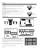
AUXILIARY SWITCH SETUP
Note: This table shows the auxiliary switch action based on the dip switch 1 and 7 settings. You should program the dip switches on the
actuator based on the application requirements, once programmed review this chart to determine the action of the auxiliary switches and
wire the switches accordingly. IF YOU CHANGE EITHER DIP SWITCH 1 or 7 TO GET A DIFFERENT CONTACT CLOSURE YOU WILL
CHANGE THE EXTEND/RETRACT MOVEMENT OF THE ACTUATOR.
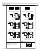
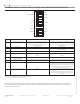
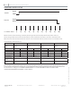
Switch 1
Switch 2
OPEN
CLOSE
OPEN
CLOSE
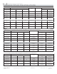
0
10 20
30 40
50
60 70 80 90 100
% of Value Travel