
Selection Guide


F-27490-4 © Copyright 2008 TAC. All rights reserved. 5
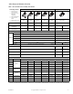
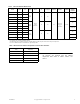
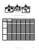
Table-3 TAC Forta Actuator Model Chart
Model
Actuator
Code
Linkage
Kit
Force,
lbf (N)
Power
Running
VA
Transformer
Sizing VA
Floating
Control
a
a
DIP switch selectable.
Proportional
Control
a
Feedback
(2) SPDT
Auxiliary
Switches
M400A
c
—
b
AV-811
c
90
(400)
24 Vac
±10%
50/60 Hz
630
Yes
0-10 Vdc,
2-10 Vdc,
or
4-20 mAdc
2-10 Vdc
No
M400A-VB 674 —
M400A-S2
c
—
b
b
No actuator code. No factory assemblies offered.
AV-811
c
24 Vac 4A
M400A-S2-VB —
b
—
M800A
c
—
b
AV-811
c
180
(800)
15 50
No
M800A-VB 680 —
M800A-S2
c
—
b
AV-811
c
24 Vac 4A
M800A-S2-VB —
b
—
M1500A
cd
c
AV-811 linkage (order separately) required for mounting actuators to VB-7xxx globe valve bodies using U-Bolt style Forta.
—
b
AV-811
c
337
(1500)
15 50
No
M1500A-VB
d
d
Do not use M1500 actuators on VB-7323 three way diverting valves.
686 —
M1500A-S2
cd
—
b
AV-811
c
24 Vac 4A
M1500A-S2-VB
d
—
b
—
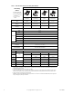
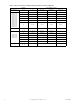
Table-4 Restrictions on Ambient Temperature for Forta Valve Actuators
Fluid Temperature in Valve
Body
Maximum Allowable Ambient
Temperature
a
a
Minimum allowable ambient operating temperature 14°F (-10°C)
Chilled Water 122°F (50°C)
281°F (138°C) 113°F (45°C)
300°F (149°C) 107°F (42°C)
340°F (171°C) 100°F (38°C)
366°F (186°C) 90°F (32°C)
Note: When installing valve and actuator assemblies, observe
the minimum and maximum fluid and ambient
temperature limits shown in Table-1, Table-2, and
Table-4.