
User Guide

Schneider Electric 1354 Cliffo rd Ave. Loves Park, IL 61111 1-888 - 44 4 -1311 w ww.schneider-electric.co m / buildings
F-27599-4 March 2011 co
© 2011 Schneider Electric. All rights reserved.
3
Globe Valve Actuators & Assemblies
Forta
FUNCTION
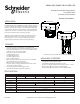
The actuator
The brushless DC-motor of the actuator turns a screw via a gear wheel. When the motor
receives a control signal from the controller, the screw moves in a linear motion, moving the
stem of the valve.
Control signal
The M400A (VB)/ M800A (VB)/ M1500A (VB) Series can be controlled by a SPDT oating
control, Triac source controller or a proportional input signal.
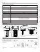
Manual operation
There is a red manual operation handle on the actuator. When it is lowered, the motor stops.
Then the actuator can be operated manually if the handle is turned.
Note: Actuator is shipped with manual override lowered (MAN). For normal operating, the
handle must be raised (AUTO).
Position feedback
M400A (VB), M800A (VB), and M1500A (VB) actuators are equipped with a 2-10 Vdc posi-
tion feedback.
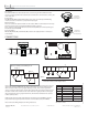
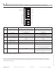
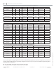
CONNECTIONS
Block Function Description
G
24 Vac or 24 Vdc Com
Power
H
24 Vac or +24 Vdc
Power
AI
+
Input Signal
C
-
Signal Common
D1
Floating
Extend/Retract**
D2
Floating
Extend/Retract**
AO
+
Feedback Signal
** Exact Operation will vary based on the settings of
DIP switch #1 and #7.
Note: For oating input signals the cables between the controller and the Forta should not
exceed 328’ (100m) (16 AWG) with the cables connected to one actuator. When installed
with 3 conductors with very long lengths ( oating control), where control signal refer-
ence is connected to G, the motor current of the actuator will cause varying voltage loss in
the cable and thus in the reference level. Forta which has a highly sensitive control signal
input, will detect the varying signal and follow it, which makes it di cult for the actuator
to nd a stable position.
Cable Lengths: The wires to G, H should be max of 328 ft (100m). min AWG 16, all other
proportional input signal input wires should be a max of 656 ft (200m) min AWG 20.
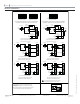
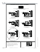
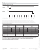
Please refer to the Wiring Examples for wiring instructions.
1
2
3
4
56
7
8
9
A0 AI C D1 D2 G H
Optional Auxiliary Switch Outputs S2
Relay 1
K1
K2 KC1
Relay 2
K3
K4 KC2
A0
A1
C
D1
D2 G
H
*
* Provides 16 Vdc, 25 mA output source
24 Vac
NORM
NORM
INV
INV
AI
AI D1D2 D1D2
0(2)V
0(2)V
10V
10V
Red Manual
Override Lever-
Raised (Auto)
Red Manual
Override Lever-
Lowered (Manual)