
User Guide

Schneider Electric 1354 Clifford Ave. Loves Park, IL 61111 1-888-444-1311 www.schneider-electric.com
F-27599-2 June 2010 dl
© 2010 Schneider Electric. All rights reserved.
11
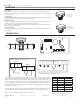
Globe Valve Actuators & Assemblies
Forta
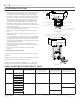
ACTUATOR INSTALLATION
U-Bolt Forta
Screw-Mount Forta
Actuator Linkage Slot
Stem Adaptor
Actuator Stem Height
Valve Nut
Top of the Actuator Yoke Slot
Red Manual Override Lever
Shown in Power On Position
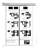
Note: Clockwise and Counter-Clockwise directional orientation in the installation instruction is
described from the underside of the actuator , not from the view above.
Stem Nut
Screw Mount Forta: Valve Installation
With the red manual override lever in the down position, slide 1.
stem adapter into actuator linkage slot. The stem adapter acts
as a gauge to set the correct height of the actuator linkage.
Turn the red manual override lever to adjust the actuator link-2.
age height so the tip of the stem adapter is even with the top
of the actuator yoke slot (typically this is around 7/8”) and
then turn the red manual override lever two additional turns
counterclockwise (looking from the bottom of the actuator).
Install stem nut all the way on to the valve stem, remove the 3.
stem adapter from the actuator linkage slot and install it all the
way on the valve stem.
Tighten stem adapter with a 7/16 inch wrench and nut with a 4.
5/16 inch wrench and pull valve stem up.
Slide actuator linkage slot sideways into valve stem adapter 5.
groove.
Push actuator onto valve body. Finger-tighten the valve nut 6.
until threads catch.
To create plug and seat clearance before final assembly tighten-7.
ing, rotate red manual override lever clockwise four to six turns
(looking from the bottom of the actuator). If you skip this step,
you may have trouble getting the valve tight onto the actuator
and risk damaging equipment.
Tighten valve nut into actuator base. You may need to use 8.
TOOL 37, 1-5/8” offset open end wrench to ensure the actua-
tor is tightly fastened.
Release the red manual override lever to allow actuator 9.
operation.
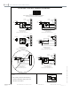
U-Bolt Mount Forta: Valve Installation
Follow instructions for AV-811 or AV-812 valve adaptor (ordered
separately):
F-27442: AV-811 VB-7xxx series globe valve linkage kit required for
M400A, M800A and M1500A actuator mounting.
F-27443: AV-812 VB-9313 and VB-8XXX 2-1/2” - 6” globe valve
linkage kit required for M800A and M1500A actuator mounting.
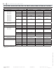
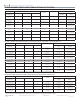
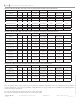
Connection Part Number VB-7000 1/2 “ to 2”
Bronze Direct Mounted
VB-7000 1/2” to 2” Bronze
Requires AV-811 Linkage
Purchased separately
VB-8000 2-1/2” to 6” Iron
Requires AV-812 Linkage
Purchased separately
VB-9313 2-1/2” to 6” 3 way
mixing Iron Requires AV-812
Linkage Purchased seperately
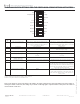
Screw-Mount M400A-VB
Yes — — —
M400A-S2-VB
M800A-VB
M800A-S2-VB
M1500A-VB
M1500A-S2-VB
U-Bolt Mount M400A
— Yes
—
—
M400A-S2
M800A
Yes
M800A-S2
M1500A
Yes
M1500A-S2
GLOBE VALVE/FORTA COMPATIBILITY TABLE