
Manual

Schneider Electric 1354 Clifford Ave. Loves Park, IL 61111 1-888-444-1311 www.schneider-electric.com
F-27599-2 June 2010 dl
© 2010 Schneider Electric. All rights reserved.
Globe Valve Actuators & Assemblies
Forta
6
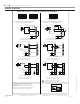
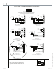
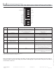
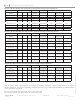
PROGRAM SWITCH SETTINGS FOR THE FORTA NON-SPRING RETURN ACTUATORS
Switch Set-
ting
Description Off Position
1
On Position
1 Valve closing screw direction After power up, actuator will retract fully before the
input control signal takes control. This switch will change
the proportional or floating input signal to direct or
reverse action similar to switch 7.
After power up, actuator will extend fully before the input
control signal takes control. This switch will change the
proportional or floating input signal to direct or reverse action
similar to switch 7.
2 Control mode Proportional signal. Floating signal.
3 Sequence operation
2
Normal operation. SW 2 off, SW 3 on, SW 4 select base range (0-10 or 2-10)
SW 5 select sequence range.
4 Input voltage range 0 to 10 Vdc. 2 to 10 Vdc.
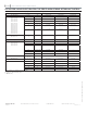
5 Working voltage range
3
0 to 5 Vdc
or
2 to 6 Vdc.
5 to 10 Vdc
or
6 to 10 Vdc.
6 Running time
(floating control only)
60 sec. 300 sec.
7 Direction of movement This switch will change the proportional or floating input
signal to direct or reverse action similar to switch 1.
This switch will change the proportional or floating input
signal to direct or reverse action similar to switch 1.
8 Linearization Normal. Used to adjust the actuator’s linear or logarithmic characteris-
tics. With this setting, the characteristics of an equally modi-
fied percentage valve can be modified to almost linear and
a linear valve can operate with “quick open” characteristics
based on the application requirements.
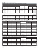
9 Input signal/ Stroke Calibration Normal Used to calibrate the input control signal and the valve
stroke. With the actuator powered, turn switch nine on, then
off. The actuator will match the control input signal to the
valve stroke. Note: Switch 9 must be in the off position for
normal operation.
1 Units are shipped with all nine switches in a default “off” position.
2 Switch 3 must be in the off position if sequence control is not used.
3 Switch 5 is only active if switch 2 is off and switch 3 is on.
Note: For the actuator to register new settings of the switches, the supply voltage must be removed by cutting power to the actuator or
lowering the manual override lever, then change any of switches one through eight as required and then restore power to the actuator or
raise the manual override level.
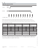
1
2
3
4
5 6
7
8
9
IN
OUT
Proportional
Floating
Sequence
0-10
2-10
0-5, 2-6
5-10, 6-10
60 sec.
300 sec.
Normal
Inverse
Normal
LIN/LG
OP ADJ
OFF
ON