
Manual

Schneider Electric 1354 Clifford Ave. Loves Park, IL 61111 1-888-444-1311 www.schneider-electric.com
F-27599-2 June 2010 dl
© 2010 Schneider Electric. All rights reserved.
Globe Valve Actuators & Assemblies
Forta
12
On October 1st, 2009, TAC became the Buildings business of its parent company Schneider Electric. This document reflects the visual identity of Schneider Electric,
however there remains references to TAC as a corporate brand in the body copy. As each document is updated, the body copy will be changed to reflect appropriate
corporate brand changes.
FEDERAL COMMUNICATION COMMISSION (FCC)
Note: This equipment has been tested and found to comply with the limits for class B digital device, pursuant to Part 15 of the
FCC Rules. These limits are designed to provide reasonable protection against harmful interference in residential installations.
This equipment generates, uses, and can rediate radio frequency energy and may cause harmful interference if not installed
and used in acordance with the instructions. Even when instructions are followed, there is no guarantee that interferance will
not occur in a particular setting-Which can be determined by turning the equipment off and on-the user is encouraged to try to
correct the interference by one or more of the following measures:
- Reorient or relocate the receiving antenna
- Increase the seperation between the equipment and receiver
- Connect the equipment to an outlet on a circuit different form that to which the receiver is connected
- Consult the dealer or an experienced radio/television technician for help.
CANADIAN DEPARTMENT OF COMMUNICATIONS (D0C)
Note: This class B digital apparatus meets all requirements of the Canadian Interference Causing Equipment Regulations
Cet apparel numenique de la classe respects toutes les exigences du reglement sur le material broilleur du Canada.
EUROPEAN STANDARD EN 55022
Warring: This is a class B digital (European Classification) product in a domestic environment this product may cause radio
interference in which case the user may be required to take adequate measures.
CAUTION: Avoid locations where excessive moisture, corrosive fumes, vibration, or explosive vapors are present.
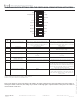
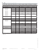
APPROVALS
The switches on the circuit board should be set before the actuator is installed. There are no other switches or potentiometers that should
be set or adjusted. Actuator travel adjustment must be set as follows upon commissioning: Actuator and valve linked, manual override lever
raised (AUTO), power on, move switch 9 (OP/ADJ) ON and then OFF. Forta closes the valve and opens it fully. The adjustment is finished
by the actuator closing the valve again; the electronic circuitry then adjusts the stroke. It also scales the actuator input signal, output feed-
back signal, and optional auxiliary switch outputs to match the valve’s travel. The set values are stored in the EEPROM of the actuator so
that they will remain after a loss of voltage. When the end position adjustment is complete, the actuator starts to control the valve accord-
ing to the control signal.
Note: Switch 9 (OP/ADJ) must be in the off position for normal operation.
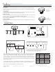
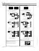
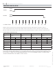
ELECTRICAL CONNECTIONS
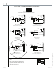
ACCESSORIES
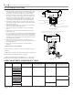
U-Bolt Mounting Style Only (M400A, M800A, M1500A Only):
AV-811 VB-7xxx series globe valve linkage kit required for M400A, M800A, and M1500A actuator mounting. Order separately, F-27442.
AV-812 Globe valve linkage kit required for mounting M800A actuators to 2-1/2 to 4 inch VB-9313 and the M1500A actuators to either
the 2-1/2” to 6” VB-9313 series globe valves and the 2-1/2” to 6” VB-8000 series globe valves. Order separately, F-27443.
U-Bolt or Screw Mount Styles (M400A (VB)/M800A (VB)/M1500A (VB) Styles):
AV-800 series globe valve adapters (competitor valves). F-27470