
User Guide


Copyright 2006, TAC
All brand names, trademarks and registered
trademarks are the property of their respective
owners. Information contained within this
document is subject to change without notice.
F-24579-2
www.tac.com
TAC
1354 Clifford Avenue
P.O. Box 2940
Loves Park, IL 61132-2940
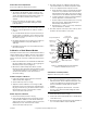
4. Slowly increase the main air pressure until the branch
tap gauge drops to 0 psig. This is the main air pressure
at which the thermostat switches from summer control to
winter control.
5. If the main air pressure at the switching point is less than
17 psig or greater than 21 psig, adjust the switching
screw as follows, using a 20-881 thermostat wrench
(1/16” hex wrench):
a. If the switching point is less than 17 psig, turn the
switching screw 1/8 turn counterclockwise, to raise
the switching point. Raise the main air pressure until
the branch tap gauge reading drops to 0 psig
(switching point). If the main air pressure at this point
is still less than 17 psig, repeat this step, as
necessary, until the switching point is obtained.
b. If the switching point is greater than 21 psig, turn the
switching screw 1/8 turn clockwise, to lower the
switching point. Lower the main air pressure until the
branch tap gauge reading drops to 0 psig (switching
point). If the main air pressure at this point is still
greater than 21 psig, repeat this step, as necessary,
until the switching point is obtained.
Caution:
Do not force the calibrating screws. If the desired
action is not obtained when the screw is rotated, check to be
sure the direction of rotation is correct.
6. Reinstall the thermostat cover and set the thermostat to
the desired setpoint.
Concealed Adjustment
If concealment of the setpoint adjustment is required, install
a 21-800 (black) or 21-801 (Euro-white) setpoint adjustment
cover as follows:
1. Remove the thermostat cover.
2. Insert the adjustment cover through the slot at the top of
the cover and bend the tangs outward on the inside of
the cover.
3. Reinstall the cover onto the thermostat.
Internal Stop Kit (Accessory)
The internal stop kit, model 20-712, consists of two screws
and two nuts (Figure-9 and Figure-10). Install this kit as
follows:
1. Move the setpoint adjustment to one extreme limit.
2. Place a nut in the depression in the top plate and move
the adjustment cam over the nut, to where the slot in the
cam exposes the threads of the nut.
3. Thread a stop screw into the nut far enough to allow the
stop to slide in the slot. Repeat on the other side.
4. Move the setpoint adjustment to the desired
temperature, using the internal setpoint indicator.
5. Slide the stops to the desired limits and tighten both
screws.
MAINTENANCE
The thermostat requires no maintenance.
Regular maintenance of the total system is recommended to
assure sustained, optimum performance.
FIELD REPAIR
None. Replace an inoperative thermostat with a functional
unit.
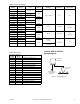
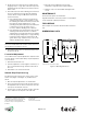
DIMENSIONAL DATA
1-1/4
(3.18)
1-3/8
(3.5)
1/8
(.318)
1-3/8
(3.5)
2-1/32
(5.16)
2-1/32
(5.16)
MB
Dimensions are in inches (mm).
Figure-11 Mounting Dimensions.