
User Guide


6 © Copyright 2006 TAC All Rights Reserved. F-24579-2
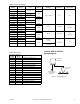
Optional Mounting
Eliminate the pipehead fitting by using the 22-022 thermostat
conversion kit and the included instructions, plus the
following:
1/4" Plastic Air Lines: Install the 1/4" barbed couplings into
the air lines. Connect the tube assembly to the 3/16" end of
these couplings.
1/4" Copper Air Lines: Solder the barbed couplings into the
copper lines. The tube assembly can then be connected to
the 3/16" end of the couplings.
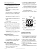
CALIBRATION
Calibration of Single Bimetal Models
The 2218 series thermostats are factory calibrated with the
throttling range set at 3 °F. They should not require
calibration upon installation. However, if the throttling range
is changed, or if limited summer control action at 8 psig main
air pressure is required, recalibrate the thermostat as follows:
1. Remove the thermostat cover and install a 22-138 branch
tap gauge adaptor into the branch pressure tap hole
(Figure-9).
2. Measure the ambient temperature with an accurate
thermometer. This temperature
must be within the range
of the thermostat
. Take care not to breathe on, or place
a hand near the bimetals, as this will result in an
inaccurate reading.
3. Move the setpoint adjustment to the measured ambient
temperature, using the internal setpoint indicator.
¡
F
¡
C
5
2
1
2
6
2
Branch
Main
Polyethylene
Tubing
Air Supply
Cutouts
(partially formed
on underside)
20-689
Mounting Fitting with
8 ft. Copper Lines
(order separately)
20-716
Insulating Back Plate
(order separately)
20-693
6 in. Tube Assembly
with Eyelets
(included with
thermostat)
Cover
(order separately)
20-642
Mounting Ring and
Flathead Screws
(order separately)
Thermostat
Mounting Screws
(included with thermostat)
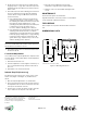
Figure-8 Surface Mounting of Thermostat,
Pipehead Application.
Standard Calibration
1. Taking care not to breathe on, or place the hand near the
bimetal, use a 20-881 thermostat wrench (1/16” hex
wrench) to turn the reverse acting calibration screw until
the branch line pressure indicates 12 psig. Clockwise
rotation increases the branch line pressure.
Counterclockwise rotation decreases the branch line
pressure.
2. Raise the main air pressure to 25 psig.
3. Turn the direct acting calibration screw until the test
gauge indicates 12 psig. Clockwise rotation decreases
the branch line pressure. Counterclockwise rotation
increases the branch line pressure.
Special Calibration — 8 psig Summer Control
1. Set the main air pressure to 8 psig.
2. Taking care not to breathe on, or place the hand near the
bimetal, use a 20-881 thermostat wrench (1/16” hex
wrench) to turn the reverse acting calibration screw until
the branch line pressure indicates 6 psig. Clockwise
rotation increases the branch line pressure.
Counterclockwise rotation decreases the branch line
pressure.
3. Raise the main air pressure to 25 psig.
4. Turn the direct acting calibration screw until the test
gauge indicates 6 psig. Clockwise rotation decreases the
branch line pressure. Counterclockwise rotation
increases the branch line pressure.
˚F ˚C
5
2
12
6
2
T R
H
Internal Setpoint
Indicator
Branch
Pressure
Tap
Setpoint Adjustment
Thermostatic
Bimetal
Reverse Acting
Calibration Scre
w
Cover Scale
Setpont Indicator
Celsius
Scale
Fahrenheit
Scale
Limit Stops (2)
(Accessory)
Throttling Range
Adjustment Slide
Switch-over
Calibration Screw
Direct Acting
Calibration Screw
Figure-9 Single Bimetal Thermostat Calibration
Features and Limit Stop Accessory.