
Installation Guide

Installation and Operating Instructions
Duct and Outside Air Humidity with Optional Temperature Sensor
Building Automation Products, Inc., 750 North Royal Avenue, Gays Mills, WI 54631 USA
Tel:+1-608-735-4800 • Fax+1-608-735-4804 • E-mail:sales@bapihvac.com • Web:www.bapihvac.com
49483_ins_duct_OSA_humidity
4 of 4
rev. 11/17/22
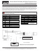
Humidity Output DIP Switch Note:
The transmitter circuit board may have a three-
position DIP switch that controls the humidity
output value. This switch is set at the factory at
the time of the order. The settings of the switch
are shown at right in case you want to change
them in the eld. Be aware that the power
requirements for the unit change depending
on the humidity output value. See the
specications section for power requirements.
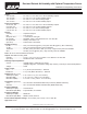
Temperature Diagnostics
Humidity Diagnostics
Possible Solutions:
- Conrm the input is set up correctly in the controller’s software
- Verify that the sensor wires are not physically shorted or open
- Check wiring for proper termination
- Measure the temperature at the temperature sensor’s location using an accurate
temperature standard. Disconnect the temperature sensor wires and measure the
temperature sensor’s resistance with an ohmmeter. Compare the temperature sensor’s
resistance to the appropriate temperature sensor table on the BAPI website. If the
measured resistance is dierent from the temperature table by more than 5%, call BAPI
technical support. BAPI’s web site is found at www.bapihvac.com; click on “Resource
Library” and “Sensor Specs” then click on the type of sensor you have.
Possible Problems:
Unit will not operate
Humidity output is at its maximum
Humidity output is at its minimum
Humidity reading in controller’s
software appears to be o by
more than the specied accuracy
Output Humidity Formula
4 to 20mA %RH =(mA-4)/0.16
0 to 5VDC %RH = V/0.05
1 to 5VDC %RH = (V-1)/0.04
0 to 10VDC %RH = V/0.1
2 to 10VDC %RH = (V-2)/0.08
Possible Solutions:
- Check for proper supply power. (See page 2 for wiring diagram and power
specications)
- Make sure the humidity sensor is wired properly.
- Verify humidity with a reference sensor. If humidity drops to 5% or below in the
environment, the output will go to the maximum value.
- Make sure the humidity sensor is wired properly.
- Check all software parameters
- Determine if the sensor is exposed to an external air source dierent from the
intended measured environment or reference device.
- Check the Humidity transmitter output against a calibrated reference such as a
2% accurate hygrometer. Measure the humidity at the sensor’s location using the
reference meter, then calculate the humidity transmitter output using the humidity
formula at left. Compare the calculated output to the actual humidity transmitter
output (see the wiring diagram on page 2 for the humidity transmitter output wire
colors). If the calculated output diers from the humidity transmitter output by more
than 5%, contact BAPI technical support.
Possible Problems:
Controller reports Incorrect
temperature
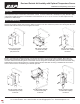
Filter Care
A sintered lter protects the humidity sensor from various airborne particles and may need periodic cleaning. To do this,
gently unscrew the lter from the probe. Rinse the lter in warm soapy water and rinse until clean. A nylon brush may be
used if necessary. Gently replace the lter by screwing it back into the probe. The lter should screw all the way into the
probe. Hand tighten only. If a replacement lter is needed, call BAPI.
BA/HDOFS3: Stainless Steel Sintered Filter Replacement for Outside Air Units
The black square represents the switch position, i.e., the “0-5 Vout”
has all switches in the “o” position