5500-Lb. Capacity Multi-Directional Pallet Jack Owner’s Manual WARNING: Read carefully and understand all ASSEMBLY AND OPERATION INSTRUCTIONS before operating. Failure to follow the safety rules and other basic safety precautions may result in serious personal injury.
Thank you very much for choosing a Bannon™ product! For future reference, please complete the owner’s record below: Serial Number/Lot Date Code: ________________________________ Purchase Date: ____________________________________________ Save the receipt, warranty, and this manual. It is important that you read the entire manual to become familiar with this product before you begin using it. This pallet jack is designed for certain applications only.
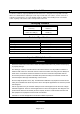
Table of Contents Intended Use .......................................................................................................................................... 4 Packaging Contents .............................................................................................................................. 4 Technical Specifications ...................................................................................................................... 4 Important Safety Information .................
Intended Use The Bannon 5500 Lb. Capacity Multi-Directional Pallet Jack is designed for transportation of loads with a level, attached base and may be used only on a firm and even surface, such as concrete or asphalt. The load must be on evenly distributed pallets, with the ideal loading mode such that the center of gravity of the load is at the central position of the fork.
WORK AREA SAFETY Inspect the work area before each use. Keep work area clean, dry, free of clutter, and well-lit. Cluttered, wet, or dark work areas can result in injury. Using the product in confined work areas may put you dangerously close to cutting tools and rotating parts. Do not allow the product to come into contact with an electrical source. The tool is not insulated and contact will cause electrical shock. Keep children and bystanders away from the work area while operating the tool.
Do not operate a loaded pallet jack on ramps or inclines. Keep the load centered on the pallet jack. Wear steel toed boots while operating the pallet jack. Check for damaged parts before operating. Do not operate a damaged or faulty pallet jack. Do not attempt repairs unless you are trained or authorized to do so. Operate a pallet jack from a designated operating position. Keep hands, feet, and other body parts clear from the lifting mechanism and under the forks of the pallet jack.
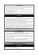
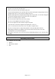
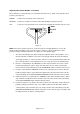
1. Insert the base of the handle into the pump bracket (Figure 1). Align the holes at the base of the handle with the holes in the pump bracket. 2. Use a hammer to tap the handle pin into the holes of the pump bracket and handle (Figure 2). Use pliers to turn the handle pin until its holes align with the spring pin holes. 3. Feed the screw head through the center hole in the handle pin (Figure 3). Using a screwdriver, pry up the cam and slip the screw head under the notch in the cam.
4. Use a hammer to tap the spring pins (Figure 2) into the holes on the pump bracket and handle pin. 5. Tap out the pump retainer pin (Figure 1). NOTE: It is a good idea to remove any air bubbles that might have accumulated in the hydraulic system during shipping. Refer to “BLEEDING THE AIR” in the maintenance section. Operating Instructions ⚠WARNING To avoid serious bodily injury or death, and/or property damage, do not exceed the rated load capacity.
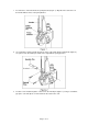
Adjusting the Control Handle - 3 Positions On the Handle (1) of this pallet jack, you can find the Control Lever (7), which can be placed in three positions (See Figure 4): LOWER - to lower the load, pull up on the control lever. NEUTRAL - to place the control lever in this position while pulling the pallet jack or load. LIFT - to raise the load, push down on the control lever and pump the handle to raise the load.
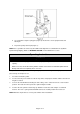
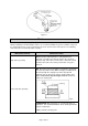
Figure 5 Maintenance Maintain the product by adopting a program of conscientious repair and maintenance in accordance with the following recommended procedures. It is recommended that the general condition of any tool be examined before it is used. Keep handles dry, clean, and free from oil and grease. The following chart is based on a normal operation schedule.
Maintenance Interval Maintenance Point BLEEDING THE AIR. There may be times when the forks do not rise while pumping when in the "LIFT" position. Most likely this is because air has been introduced in to the hydraulic system. The air can be removed by moving the control handle to the "LOWER" position, then pumping the handle up and down several times. Repeat this process until the forks lift as intended.
Troubleshooting Failure Hydraulic unit does not lift Once lifted, truck lowers by itself Fork does not lower Lever does not stay in the neutral position Possible Cause Corrective Action Low oil level. Make sure there is no oil leakage from Release Screw (35), Pressure Adjustment Screw (33) or valve area. Then add oil. Air in pump. See ''BLEEDING THE AIR''. Worn O-ring in ram cylinder. Replace O-ring (refer to ''Seal and ORing Replacement''). Air comes into the oil. See ''BLEEDING THE AIR''.
Parts Diagram Parts List Reference 1 2 3 4 5 6 7 8 9 10 11 12 13 14 15 16 17 18 19 20 21 22 23 24 25 26 27 28 29 30 Part Number 1 2 3 4 5 6 7 8 9 10 11 12 13 14 15 16 17 18 19 20 21 22 23 24 25 26 27 28 29 30 Part Description Handle Spring Pin Blade Spring Spring Pin Roller Lever Mat Lever Mat Spring Pin Control Lever Oil Lite Bushing Release Rod Pressure Roller Spring Pin Oil Lite Bushing Handle Pin Spring Pin Cam Spring Pin Hex Nut Socket Head Cap Screw Table Pin Spring Pin Table Snap Ring Ball Bearing
Reference 31 32 33 34 35 36 37 38 39 40 41 42 43 44 45 46 47 48 49 50 51 52 53 54 55 56 57 58 59 60 61 62 63 64 65 66 67 68 69 70 71 72 73 74 75 76 77 78 79 80 81 82 83 84 85 86 87 Part Number 31 32 33 34 35 36 37 38 39 40 41 42 43 44 45 46 47 48 49 50 51 52 53 54 55 56 57 58 59 60 61 62 63 64 65 66 67 68 69 70 71 72 73 74 75 76 77 78 79 80 81 82 83 84 85 86 87 Part Description Snap Ring Dust Seal Cap Pressure Adjust Screw Copper Washer Release Screw Spring Spring Base Steel Ball O-Ring Release Nozzle Bas
Reference 88 89 90 91 92 93 94 95 96 97 98 99 100 Part Number 88 89 90 91 92 93 94 95 96 97 98 99 100 Part Description Spring Pin Oiler Rod Pin Spring Spring Pin Wheel Frame V Nut Screw Spring Pin Nog Ball Bearing Wheel Wheel Axle Qty. 2 4 2 4 2 2 4 4 2 2 4 2 2 Remark Replacement Parts For replacement parts and technical questions, please call Customer Service at 1-800-222-5381. Not all product components are available for replacement.
Limited Warranty Northern Tool and Equipment Company, Inc. ("We'' or ''Us'') warrants to the original purchaser only (''You'' or ''Your'') that the Bannon product purchased will be free from material defects in both materials and workmanship, normal wear and tear excepted, for a period of two years from date of purchase. The foregoing warranty is valid only if the installation and use of the product is strictly in accordance with product instructions.
Distributed by: Northern Tool & Equipment Company, Inc. Burnsville, Minnesota 55306 www.northerntool.