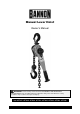
Manual Lever Hoist Owner’s Manual WARNING: Read carefully and understand all ASSEMBLY AND OPERATION INSTRUCTIONS before operating. Failure to follow the safety rules and other basic safety precautions may result in serious personal injury.
Thank you very much for choosing a Bannon™ product! For future reference, please complete the owner’s record below: Serial Number/Lot Date Code: ________________________________ Purchase Date: ____________________________________________ Save the receipt, warranty, and this manual. It is important that you read the entire manual to become familiar with this product before you begin using it. This hoist is designed for certain applications only.
Table of Contents Intended Use .......................................................................................................................................... 4 Technical Specifications ...................................................................................................................... 4 Important Safety Information ............................................................................................................... 4 Specific Operation Warnings .......................
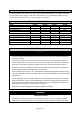
Intended Use The Bannon Manual Lever Hoist is an easily-operated, portable lifting device. It’s suitable for loading and unloading goods in garages, workshops, and warehouses. It’s a helpful tool for lifting goods in open air grounds and places where a power supply is not available. Technical Specifications Model Rated Capacity (lb.) Lift Height (ft.) Head Room (in.) Load Chain Dia. (mm) #57087 2200 5 13-3/8 5.6 #57089 2200 15 13-3/8 5.6 #57090 3300 5 12-3/4 7.1 #57091 3300 15 12-3/4 7.
may put you dangerously close to cutting tools and rotating parts. Do not use the product where there is a risk of causing a fire or an explosion; e.g., in the presence of flammable liquids, gases, or dust. The product can create sparks, which may ignite the flammable liquids, gases, or dust. Do not allow the product to come into contact with an electrical source. The tool is not insulated and contact will cause electrical shock.
before using. Disconnect the power/air supply from the product and place the switch in the locked or off position before making any adjustments, changing accessories, or storing the tool. Such preventive safety measures reduce the risk of starting the tool accidentally. Store the product when it is not in use. Store it in a dry, secure place out of the reach of children. Inspect the tool for good working condition prior to storage and before re-use.
Before Each Use ⚠WARNING Before operating, make sure that the hoist is not in the free chain mode and always check that the selector is placed in the proper position. DO NOT touch or operate the hoist’s free knob while a load is applied to the hoist. Inspect for damaged parts before use. Do not use if damaged. Examine each chain link for damage or weak links before use. Do not operate a hoist with twisted, kinked or damaged chain. 1.
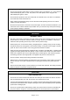
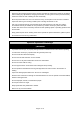
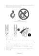
Figure C 7. It is important to check top and bottom hooks for proper opening. If the safety latch no longer contacts the hook opening, replace the hook. Never side load the top or bottom hook; this practice is dangerous and could lead to serious injury. 8. If the vertical angle at the neck of the bottom or top hook reaches 10, replace the hook (see Figure 2). Figure 1 Figure 2 9. A chain stop must be attached to the second-to-last link on the slack end of the chain (Figure 3).
Operating Instructions ⚠WARNING To reduce the risk of injury, operate hoist using manual power only. Do not exceed the rated load capacity Do not use hoist with extension on lever handle. Do not use in a way that causes either hook to be side loaded. Do not use chain hoist as a sling. Do not support load on hook unless hook is designed for tip loading. Do not operate if restricted from forming a straight line from hook to hook in the direction of loading.
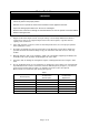
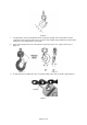
Properly seat the sling or other device in the base (bowl or saddle) of the hook (Figure 2). Do not allow the hook hitch to support any part of the load. Do not apply the load to the point of the hook (Figure 2). Figure 2 Correct and incorrect hook attachment Setting the Top Hook 1. Place the selector switch on the handle in the center neutral position, and pull out on the handwheel (Figure 4). This will allow the free-wheel mode. Pull the load chain by hand to position the bottom hook. 2.
Figure 4 Figure 5 Figure 6 Overload Protection The hoist has an overload protection feature in the form of a slip clutch. The slip clutch is effective between 1.25 to 1.55 times the hoist’s rated capacity. The slip clutch will allow the lever handle to rotate without lifting the load, if the load is too heavy for the hoist. The slip clutch was pre-adjusted at the factory and should not require any adjustment by the user. When overloaded, the hoist will not work.
Maintenance Maintain the product by adopting a program of conscientious repair and maintenance in accordance with the following recommended procedures. It is recommended that the general condition of any tool be examined before it is used. Keep your tool in good repair. Keep handles dry, clean, and free from oil and grease. The following chart is based on a normal operation schedule. Maintenance Interval Maintenance Point Daily before operating Clean hoist after each use and oil lightly.
Parts List Reference 1 2 3 4 5 6 7 8 9 10 11 12 13 14 15 16 17 18 19 20 21 22 23 24 25 26 27 28 29 30 31 32 33 34 35 36 37 38 39 40 41 42 43 44 45 46 47 48 Part Number 1 2 3 4 5 6 7 8 9 10 11 12 13 14 15 16 17 17A 18 19 20 20L 21 22 23 24 24A 25 25A 26 27 28 29 30 31 32 33 34 35 36 37 38 39 40 41 49 50 50A Part Description Gear Cover Assembly Spur Gear Assembly Drive Shaft Load Gear Gear Side Plate Assembly Caged Roller Bearings Load Sheave Guide Roller Stripper Lever Side Plate Assembly Pawl Spring Pawl
Replacement Parts For replacement parts and technical questions, please call Customer Service at 1-800-222-5381. Not all product components are available for replacement. The illustrations provided are a convenient reference to the location and position of parts in the assembly sequence. When ordering parts, the following information will be required: item description, item model number, item serial number/item lot date code, and the replacement part reference number.
Limited Warranty Northern Tool and Equipment Company, Inc. ("We'' or ''Us'') warrants to the original purchaser only ("You" or ''Your'') that the Bannon product purchased will be free from material defects in both materials and workmanship, normal wear and tear excepted, for a period of two years from date of purchase. The foregoing warranty is valid only if the installation and use of the product is strictly in accordance with product instructions.
Distributed by: Northern Tool & Equipment Company, Inc. Burnsville, Minnesota 55306 www.northerntool.