2000-Lb. Telescoping GantryCrane Owner’s Manual WARNING: Read carefully and understand all ASSEMBLY AND OPERATION INSTRUCTIONS before operating. Failure to follow the safety rules and other basic safety precautions may result in serious personal injury.
Thank you very much for choosing a Bannon™ product! For future reference, please complete the owner’s record below: Serial Number/Lot Date Code: ________________________________ Purchase Date: ____________________________________________ Save the receipt, warranty, and this manual. It is important that you read the entire manual to become familiar with this product before you begin using it. This gantry crane is designed for certain applications only.
Table of Contents Intended Use .......................................................................................................................................... 4 Packaging Contents .............................................................................................................................. 4 Technical Specifications ...................................................................................................................... 4 Important Safety Information .................
Intended Use Bannon’s 2000-Lb. Telescoping Gantry Crane allows one operator to hoist heavy items easily. It’s designed for use with a trolley hoist (not included). This crane features an I-beam that adjusts from 99" to 148"H with 9 positive stops to provide a sturdy overhead lift point for lifting car engines, heavy machinery, and other equipment. The easy crank handle allows for raising and lowering without difficulty. It rolls smoothly on 5" ball bearing casters (2 locking).
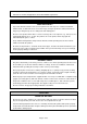
this equipment for a purpose for which it was not intended. Industrial or commercial applications must follow OSHA requirements. ⚠WARNING WORK AREA SAFETY Inspect the work area before each use. Keep work area clean, dry, free of clutter, and well-lit. Cluttered, wet, or dark work areas can result in injury. Using the product in confined work areas may put you dangerously close to cutting tools and rotating parts. Do not use the product where there is a risk of causing a fire or an explosion; e.g.
Store the product when it is not in use. Store it in a dry, secure place out of the reach of children. Inspect the tool for good working condition prior to storage and before re-use. Use only accessories that are recommended by the manufacturer for use with your product. Accessories that may be suitable for one product may create a risk of injury when used with another tool. Never use an accessory that has a lower operating speed or operating pressure than the tool itself.
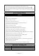
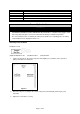
Reference 5 6 7 8 9 10 Subassembly I-Beam Post Support Gear Box Swivel Caster Locking Swivel Caster Rod Assembly Instructions ⚠WARNING TO PREVENT SERIOUS INJURY AND DEATH: Wear ANSI Z87.1 compliant safety goggles, hard hat, heavy-duty work gloves, and steel-toed work boots during assembly and operation. The correct bolts must be used during assembly. If any doubts arise regarding proper assembly, contact Northern Tool + Equipment before use.
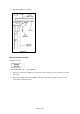
4. Repeat for right post assembly. Attaching Casters to Bases Hardware-16 each: (11)Caster Bolt M10 x 25 (13C) Nut M10 1. Attach one swivel caster (09C) to one end of base (03) using four sets of caster bolts (11),and nuts (13C). 2. Attach one locking swivel caster (09DC) to the other end of the base (03) using four sets of caster bolts (11)and nuts (13C).
3. Tighten the connections securely. 4. Repeatfor the other base, making sure that the sleeves are to the outside and thelocking swivel casters are on the same end.
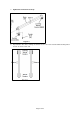
5. Apply grease to each caster bearing. Attaching Base Assemblies to Post Assemblies Hardware-8 each: (17) Post Bolt M12 x 110 (19) Washer M12 (16C) Nut M12 1. Using helpers, raise base plate ends of the post assemblies onto sawhorses or other suitable means of support. 2. Attach the left base assembly to the left post assembly by inserting the tube into the sleeve and using four sets of post bolts (17), washers (19), and nuts (16C).
3. Tighten connections securely. 4. Repeat for the right base assembly and the right post assembly. Attaching Post Supports Hardware-8 each: (14) Support Bolt M12 x 45 (19) Washer M12 (16C) Nut M12 1. Using helpers, lift the crane to an upright position. 2. Attach the post supports (05) to the left base and post the assemblies using post support bolts (14), washers (19), and nuts (16C). 3. Tighten the connections securely.
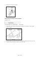
4. Repeat for the right base and post assemblies. Attaching Handles 1. Insert the handle (08C) INTO the left winch box (06C), and then tighten thescrew securely. 2. Repeat for theright winch box. 3. Once the assembly is complete, confirm that thecrane is solid and level, with all fourcasters on the floor and the I-beam perfectly level. As needed, loosen one set of connections at a time and make small adjustments with the help of an assistant so the crane is completely level.
4. Place thecrane on a solid, level surface, capable of supporting the weight of the crane and a load. Attaching the Rod 1. Insert theleft fixed shaft (26C) into theleft handle’s (08C) other side, using the hexagon set screws (12C). 2. Connect the rod (15C) with the left fixed shaft (26C), using the R-pin (30C). 3. Repeat for the right fixedshaft and rod.
Before Each Use ⚠WARNING TO PREVENT SERIOUS INJURY AND DEATH:The use of cranes is subject to certain hazards that cannot be met by mechanical means, but only by the exercise of intelligence, care, common sense, and experience in anticipating the motions that will occur as a result of operating the controls. Wear ANSI Z87.1 compliant safety goggles, hard hat, heavy-duty work gloves, and steel-toed work boots during operation.
⚠WARNING Do not adjust the legs to different heights. 3. Once the desired height has been reached, reinsert height pins and secure in place with R-pins. Before Operating Hoist 1. After desired height has been reached, secure with R-Pins, REMOVE THE ROD(15C) before operating Hoist. 2. Familiarize yourself with all operating controls of the hoist and with the operation(s) to be performed. Instructions include, the warnings on the hoist, and the safety and operating instructions portion of this manual.
Operating Instructions ⚠WARNING TO PREVENT SERIOUS INJURY AND DEATH:Use warning signs and barriers on the floor beneath the gantry crane where overhead maintenance work creates a hazard. Wear ANSI-approved safety goggles, hard hat, heavy-duty work gloves, and steel-toed work boots during operation. Always have a least 2 people operating crane at any time. Operate on a hard, level surface. Do not operate crane if the beam is not level. Do not use to lift people or animals.
4. Make sure the load and hoist will clear all obstacles before moving or rotating the load. 5. Do not lift a load more than a few inches until it is well balanced in the sling or lifting device. 6. Each time a load is handled that is approaching the rated capacity. Check the hoist brake action by lifting the load just clear of supports and continuing only after verifying that the brake system is operating properly. ⚠WARNING Do not use to lift people or animals.
Maintenance Interval Maintenance Point 1. Some components may require adjustment. The following are examples: A. Operating mechanisms B. Limit switches C. Control systems D. Brakes 2. Note the following regarding specific components: A. Replace damaged or worn hooks. Do not repair them by welding or reshaping. B. Replace or repair all critical parts that are cracked, broken, bent, excessively worn, or missing. Daily before operating 3. Do not repair load-sustaining members by welding.
Maintenance Interval Maintenance Point 1. Follow all monthly maintenance procedures. 2. Check for deformed, cracked, or corroded parts, replace them as needed. Yearly maintenance 3. Make sure all the parts as bolts,nuts,pins, or rivets are fixed well. 4. Check for other worn, cracked, or distorted parts such as pins, bearings, wheels, shafts, gears, rollers, locking and clamping devices, bumpers, and stops.
Parts Diagram Page 20 of 23
Parts List Reference 1 2 3 4 5 6 7 8 9 10 11 12 13 14 15 16 17 18 19 20 21 22 23 24 25 26 27 28 29 30 31 32 33 34 Part Number 01 02C 02CB 03 04C 05 06C 06CB 07 08C 09C 09DC 10 10-1 11 12C 13C 14 15C 16C 17 18 19 20B 21 22 23 24 25 26C 27C 28 29 30C Part Description Post Insert Post Sleeve (left) Post Sleeve (right) Base I-Beam Post Support Winch Box (left) Winch Box (Right) Height Pin Handle Swivel Caster Locking Swivel Caster Cable Wire Rope Clamp Caster Bolt Fixed Bolt Nut Post Support Bolt Rod Nut Post
Limited Warranty Northern Tool and Equipment Company, Inc. ("We'' or ''Us'') warrants to the original purchaser only ("You" or ''Your'') that the Bannon product purchased will be free from material defects in both materials and workmanship, normal wear and tear excepted, for a period of two years from date of purchase. The foregoing warranty is valid only if the installation and use of the product is strictly in accordance with product instructions.
Distributed by: Northern Tool & Equipment Company, Inc. Burnsville, Minnesota 55306 www.northerntool.