
Instruction Manual
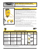


U-GAGE
™
Q45UR Remote Ultrasonic Sensors
page 7
Banner Engineering Corp. • Minneapolis, MN U.S.A.
www.bannerengineering.com • Tel: 763.544.3164
Application Notes
Operating Temperature Controller and sensor: -25 to +70°C (-13 to +158°F)
Maximum relative humidity: 85% (non-condensing)
The Teach-mode function of the controller (see page 2) is used to set the sensing distance set point. The
sensing window size is set using DIP switches #2 and #3 (page 3). The sensing distance set point is
centered within the sensing window. The size of the sensing window may be adjusted at any time, with or
without power applied, and without re-teaching the sensing distance set point.
If the sensor is taught a window larger than 5 mm, the size of the window remains “fixed,” disabling
switches 2 and 3.
The controller has non-volatile memory which remembers the last sensing distance set point setting if
power is removed and later reapplied.
The sensing distance set point may be programmed via the Remote Teach input (see hookup diagrams).
Minimum target size is specified as a 10 x 10 mm aluminum plate (at any point within the 50 to 150 mm
sensing range).
Acceptable target angle is within ±5° of normal for a smooth, flat target; target rotation does affect the
apparent target location with respect to the sensor.
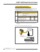
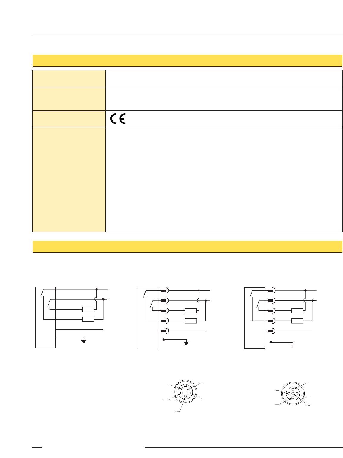
Q45UR Controller with Quick-Disconnect
(5-Pin Mini-Style)
(“Q” model Suffix)
Q45UR Controller with
Attached Cable
bn
wh
bu
+
–
bk
ye
Load
Load
12-24V dc
Remote Teach
(+5-24V dc)
shield*
bn
wh
bu
+
–
bk
ye or gy
Load
12-24V dc
Remote Teach
(+5-24V dc)
Load
shield*
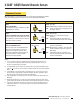
Q45UR Controller with Quick-Disconnect
(5-Pin Euro-Style)
(“Q6” model Suffix)
bn
wh
bu
+
–
bk
gy
Load
Load
12-24V dc
Remote Teach
(+5-24V dc)
shield*
5-Pin Mini-Style Pin-out
(Cable Connector Shown)
Black Wire
Blue Wire
Brown Wire
Yellow Wire
White Wire
5-Pin Euro-Style Pin-out
(Cable Connector Shown)
White Wire
Blue Wire
Black Wire
Brown Wire
Gray Wire
Q45UR Series Specifications, continued
Q45UR Series Controller Hookups
Vibration and
Mechanical Shock
All models meet Mil. Std. 202F requirements. Method 201A Vibration: 10 to 60Hz max., double amplitude
0.06" (maximum acceleration 10G). Method 213B conditions H & I (Shock: 75G with unit operating; 100G
for non-operation). Also meets IEC 947-5-2 requirements: 30G, 11 ms duration, half sine wave.
Certifications
*Shield wire must be connected to ground