
Instruction Manual


U-GAGE
™
Q45UR Remote Ultrasonic Sensors
page 6
Banner Engineering Corp. • Minneapolis, MN U.S.A.
www.bannerengineering.com • Tel: 763.544.3164
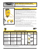
Q45UR Series Specifications
Sensing Distance Range 50 to 250 mm (2" to 10")
Supply Protection Circuitry Protected against reverse polarity and transient voltages
Output Configuration Bipolar: one current sourcing (PNP) and one current sinking (NPN) open collector transistor
Output Rating 150mA maximum (each output)
OFF-state leakage current: <25 microamps at 24V dc
ON-state saturation voltage: <1.5V at 10mA; <2.0V at 150mA
Output Protection Circuitry Protected against false pulse on power-up and continuous overload or short-circuit of outputs
Supply Voltage and Current 12 to 24V dc (10% maximum ripple) at 100mA, exclusive of load
Adjustments The following may be selected by a 4-position DIP switch located on top of the controller, beneath a
transparent o-ring sealed acrylic cover and beneath the black inner cover (see page 2):
Switch 1: Output normally open (output is energized when target is within sensing window limits), or
normally closed (output is energized when target is outside sensing window limits)
Switches 2 & 3: Sensing window size (1 mm, 2 mm, 3 mm or 4 mm; see Application Notes, page 5)
Switch 4: Response speed selection (40 or 160ms)
Performance Specifications
* Repeatablility is specified
using a 50 mm x 50 mm
(2" x 2") aluminum plate at
22ºC under fixed sensing
conditions.
Response speed: 40 or 160 milliseconds (switch selectable)
Repeatability*: ±0.2% of measured distance
Temperature stability: ±0.03% of the window limit positions per °C from 0° to 50°C
(±0.05% per °C over remainder of operating temperature range)
Sensing window width: 5 mm to 200 mm, when independent near and far limits are taught;
1, 2, 3, or 4 mm (switch selectable), when a sensing distance set point is taught
Hysteresis: 0.5 mm
Ultrasonic beam angle: ±3.5°
Also see Response Curve, page 4
Construction Controller: Molded thermoplastic polyester housing, o-ring sealed transparent acrylic top cover, and
stainless steel hardware
Sensors: M18C2.0: Stainless steel M18 threaded barrel housing and jam nuts, ULTEM
®
polyetherimide
front cover, ceramic transducer, TEXIN
®
polyurethane rear cover
S18C2.0: Thermoplastic polyester S18 threaded barrel housing and jam nuts, ULTEM
®
polyetherimide front cover, ceramic transducer, TEXIN
®
polyurethane rear cover
Q13C2.0: Molded 30% glass reinforced thermoplastic polyester housing, ceramic transducer,
fully epoxy-encapsulated
Environmental Rating Controller: IEC IP67; NEMA 6P
Sensor: IEC IP65; NEMA 4
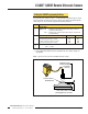
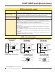
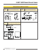
Connections Controller: 2m (6.5') or 9 m (30') attached cable, or 5-pin Mini-style or Euro-style quick-disconnect fitting
Sensor: 2m (6.5') attached PVC cable terminated with 4-pin Euro-style quick-disconnect fitting for
connection to controller
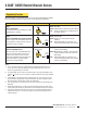
Indicators Three status LEDs:
Green ON steadily = power to controller is ON
Green flashing = output is overloaded
Yellow glowing steadily = outputs are conducting (yellow also indicates programming status during
setup; see page 3)
Red flashing = relative strength of received echo
5-segment red LED indicates the following:
#3 ON steadily = Target within sensing window
#1 flashing = Target closer than near window limit
#5 flashing = Target further than far window limit
All OFF = No target present
ULTEM
®
is a registered trademark of General Electric
TEXIN
®
is a registered trademark of Bayer Corporation