
Instruction Manual


U-GAGE
™
Q45UR Remote Ultrasonic Sensors
page 2
Banner Engineering Corp. • Minneapolis, MN U.S.A.
www.bannerengineering.com • Tel: 763.544.3164
1
ON
234
See Table Below for
Programming Information
Programming the Sensing Window Limits
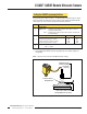
The Q45UR controller features a single push button for
programming the sensing window limits (Figure 1). The window
limits may be set in one of two ways: programming two
independent window limits, or defining a sensing distance set
point, which will be centered within a window whose size is
determined by the setting of DIP switches 2 and 3 (specific
steps are described on page 3).
Independent Window Limits: The target is placed at the desired
position to set the first limit, then the second limit is set using
the same procedure. In order to set two independent limits, the
window must be at least 5 mm.
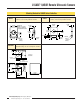
Sensing Distance Set Point: The sensor is taught the same set
point for both window limits. This set point is centered within an
overall window size of 1, 2, 3, or 4 mm (0.04", 0.08", 0.12", or
0.16"), determined by the DIP switch settings. DIP switches are
located inside the controller, under the inner cover (Figure 1).
See page 4 for detailed programming instructions.
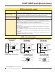
Status Indicators
Status indicator LEDs are visible through the transparent,
o-ring sealed Lexan
®
top cover. Their function is as follows:
Limits
N
1 2 3 4 5
Green Power
Indicator
Red Signal
Indicator
Yellow Output
Indicator
Sensing
Window Limits
Programming
Push Button
5-Segment Target
Position Indicator
(N = Near)
Slots for Inner
Cover Removal
Figure 1. Q45UR controller features
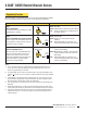
Figure 2. Q45UR controller programming DIP switches
(factory default settings)
LED Condition Description
Green
ON Steady
Flashing
Power is applied to the sensor
Overloaded output
Red Flashing
An echo is received; rate is proportional
to echo strength
Yellow ON Steady Outputs are conducting
The 5-segment moving dot LED indicator tracks the position
of the target relative to the programmed window limits.
For Independent Window Limits ( > 5 mm windows): LED #1
flashes when the target is closer than the near window limit.
LED #5 flashes when the target is beyond the far window limit.
LED #3 comes ON when the target is near the center of the two
limits.
For Sensing Distance Set Points (1, 2, 3,or 4 mm windows):
LED #1 flashes when the target is closer than the near window
limit. LED #3 comes ON steady when the target is within the
sensing window. LED #5 flashes when the target is beyond the
far sensing window.