
User guide
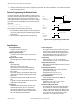

Position Response Speed Potentiometer Positions
1 80 milliseconds (2 cycles)
1
2
3 4
5
6
+
–
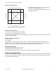
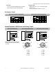
Figure 4. Response adjustment positions
This example shows the potentiometer set at position number 4. There
are no numbers on the actual product label.
2 160 milliseconds (4 cycles)
3 320 milliseconds (8 cycles)
4 640 milliseconds (16 cycles)
5 1.28 seconds (32 cycles)
6 2.56 seconds (64 cycles)
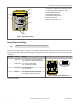
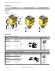
Programming the Window Limits
Use the “Limits” push button, located under the transparent top cover, to program the near and the far limits. The near limit may be set as
close as 100 mm (4 inches) and the far limit may be set as far as 1400 mm (55 inches) from the transducer face. Minimum window width
is 10 mm (0.4 inches). Whenever possible, use the actual target to be sensed when setting the window limits. The following procedure
begins with the sensor in Run mode.
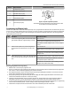
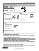
Step Description LED Indicator Status
1 Access Limit Programming Mode. Push and hold until the
green indicator LED turns off (approximately 2 seconds).
Green: Goes off
Amber: Solid on to indicate ready for teaching first limit
Red: Flashes to indicate strength of echo or is off if no target is
present
2 Set the First Limit (Near or Far). Place the target at the
first limit and press the push button for less than 2 sec-
onds.
Green: Remains off
Amber: Flashes at 2 Hz to indicate ready for teaching second
limit
Red: Solid on for a moment, then resumes flashing to indicate
strength of echo
3 Set the Second Limit (Far or Near). Place the target at the
second limit and press the push button for less than 2 sec-
onds
Green: Remains off, then comes on solid (returns to Run mode)
Amber: Solid on for a moment, then is either on or off to indi-
cate output state (returns to Run mode)
Red: Solid on for a moment, then resumes flashing to indicate
strength of echo (returns to Run mode)
Notes Regarding Window Limit Programming
1. Either the near or far limit may be programmed, first.
2. There is a 2-minute time-out for programming of the first limit. The sensor will return to Run mode with the previously programmed
limits. There is no time-out between programming of the first and second limit.
3. The programming sequence may be cancelled at any time by pressing and holding the push button for ≥ 2 seconds. The sensor
returns to Run mode with the previously programmed limits.
4. During limit programming, the 5-segment moving dot indicator displays the relative target position between 0 and 1500 mm (the
maximum recommended far limit position is 1400 mm (55 inches)).
5. If the target is positioned between 1400 mm (55 inches) and 1500 mm, the 5th segment of the moving dot indicator flashes to
indicate that a valid echo is received, but the target is beyond the recommended 1400 mm (55 inches) maximum far limit.
6. If a limit is rejected during either programming step, the sensor will revert to the first limit programming step (Step 2 in programming
chart). This will be indicated by Green - off, Red - flashing to indicate signal strength, and Amber - solid on.
7. If both limits are accepted, the sensor will return to Run mode, which is indicated by the solid on Green LED.
Q45U Ultrasonic Sensors with Analog Outputs (Short Range)
4 www.bannerengineering.com - tel: 763-544-3164 P/N 47818 Rev. E