
User guide
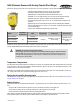

Piezoelectric analog proximity mode sensors with push-button or remote programming of sensing window limits
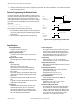
• Ultrasonic proximity detection from 100 to 1400 mm (4 to 55 inches)
• Push-button TEACH-mode programming of sensing window limits
• Digital filtering for exceptional immunity to electrical and acoustic “noise”
• Selectable 0 to 10V dc voltage sourcing or 4 to 20 mA current sourcing analog outputs
• Selectable output slope: positive or negative with increasing target distance
• Wide operating temperature range of –25 to +70 °C; all models include temperature com-
pensation
• Rugged design for use in demanding sensing environments; rated IEC IP67, NEMA 6P
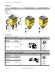
• Choose models with integral 2 m (6.5 ft) or 9 m (30 ft) cable, or with Mini-style or Euro-style
quick-disconnect fitting
• Input for remote TEACH-mode programming of window limits
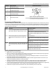
Models
Temperature
Compensation
Cable Supply Voltage Output Type Response Time
Q45ULIU64ACR
Yes
2 m (6.5 ft)
15–24V dc
Selectable 0–10V dc or 4–
20 mA sourcing
Adjustable from 40
milliseconds to 1.28
seconds
Q45ULIU64ACRQ 5-Pin Mini-style QD
Q45ULIU64ACRQ6 5-Pin Euro-style QD
Standard 2 m (6.5 ft) cable models are listed. To order the 9 m (30 ft) cable model, add suffix "W/30" to the cabled model number. For
example, Q45ULIU64ACR W/30. Models with a QD connector require a mating cable.
WARNING: Not To Be Used for Personnel Protection
Never use this device as a sensing device for personnel protection. Doing so could lead to serious
injury or death. This device does not include the self-checking redundant circuitry necessary to allow its
use in personnel safety applications. A sensor failure or malfunction can cause either an energized or de-
energized sensor output condition.
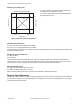
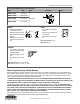
Temperature Compensation
All models listed above feature temperature compensation. An increase in air temperature shifts both sensing window limits closer to the
sensor. Conversely, a decrease in air temperature shifts both limits further away from the sensor. The shift is approximately 3.5% of the
limit distance for a 20 °C change in temperature.
Temperature compensated models maintain the position of both sensing window limits to within 1% of each limit distance over the 0 to
+50 °C range, and to within 2.5% over the full operating range of from –25 to +70 °C.
Setting the Near and Far Sensing Limits
The Q45U features a single push button for programming of sensing window near and far limits. For more information, refer to Program-
ming the Window Limits on page 4.
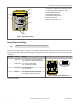
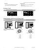
Status Indicators
Status indicator LEDs are visible through the transparent, o-ring sealed acrylic top cover. Indicator function in the Run mode is, as fol-
lows:
• The green LED is solid when power is applied to the sensor and flashes to indicate a current output fault.
• The red LED is solid when an echo is received and flashes at a rate proportional to echo strength.
• The amber LED is solid when the target is within the operating window limits.
The 5-segment moving dot LED indicator displays the relative position of the target within the programmed sensing window. LED #1
flashes when the target is closer than the near limit. LED #5 flashes when the target is beyond the far limit.
Q45U Ultrasonic Sensors with Analog Outputs (Short Range)
P/N 47818 Rev. E 10/15/2013