
Instruction Manual

• The green LED is solid when power is applied to the sensor and flashes to indicate a current output fault.
• The red LED is solid when an echo is received and flashes at a rate proportional to echo strength.
• The amber LED is solid when the target is within the operating window limits.
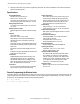
The 5-segment moving dot LED indicator displays the relative position of the target within the programmed sensing window. LED #1
flashes when the target is closer than the near limit. LED #5 flashes when the target is beyond the far limit.
Limits
N
1 2 3 4 5
3
4
5
1
2
7
Resp.
Speed
+
–
6
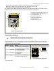
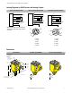
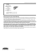
Figure 1. Analog Q45U Features
1 - Push button for programming sensing window limits
2 - 5-segment target position indicator (N = near)
3 - Green POWER indicator LED
4 - Red SIGNAL indicator LED
5 - Amber OUTPUT indicator LED
6 - Response adjustment
7 - Slots for removing inner cover
Output Response Settings
Important: Remove power before making any internal adjustments.
Using the two slots shown in Figure 1. Analog Q45U Features on page 2, a small flat-blade screwdriver may be used to lift up and
remove the black inner cover to expose the 4-position DIP switch. Use these DIP switches to program the output slope, output mode,
loss of echo, and min./max. output value default.
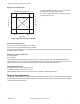
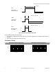
DIP Switch Function Settings
1 Output slope On = Output value increases with distance
Off* = Output value decreases with distance
1
ON
2 3 4
Figure 2. DIP Switches for Q45U Sensors
2 Output mode On = Current output enabled
Off* = Voltage output enabled
3 Loss of echo On = Min - Max Mode
Off* = Hold Mode
4 Min-Max On* = Default to maximum output value
Off = Default to minimum output value
* Factory default setting.
Q45U Ultrasonic Sensors with Analog Outputs (Long Range)
2 www.bannerengineering.com - tel: 763-544-3164 P/N 48456 Rev. E