
User guide

Apparent Temperature
Two factors that have a large influence on apparent temperature are the object’s emissivity and whether or not the object fills the sensor’s
field of view.
Object Emissivity:
A “blackbody” is a “perfect” emitter, with an emissivity of 1.0 at all temperatures and wavelengths. Most surfaces emit only a
fraction of the amount of thermal energy that a blackbody would. Typical T-GAGE applications will be sensing objects with
emissivities ranging from 0.5 to 0.95. Many references are available with tables of emissivity coefficients for common materi-
als. In general, shiny unpainted metals have low emissivity, while non-glossy surfaces have high emissivity.
Shiny surfaces: a mirror or shiny surface can redirect an object’s emitted energy to an undesired location, or even bring
additional unintended thermal energy into the sensor’s field of view (see Application Note on page 6).
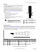
Object Size:
If the object being detected does not fill the sensor’s field of view, then the sensor will average the temperature of that object
and whatever else is in the sensing field of view. For the sensor to collect the maximum amount of energy, the object should
completely fill the sensor’s field of view. However, in some applications, when the object is too small, this may not be possi-
ble. In such cases, if the object is hot enough, the thermal contrast may still be adequate to trigger the sensor’s output.
Alarm Output
The alarm output will activate when the analog output is at 10V or 20mA, depending on model (see Figure 3. Analog/Alarm outputs as a
function of taught conditions on page 3).
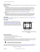
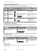
Analog Output
The T-GAGE analog sensor can be programmed for either positive or
negative output slope, based on the teach order (see Figure 3. Analog/
Alarm outputs as a function of taught conditions on page 3). If the cold
limit is taught first, the slope will be positive; if the hot limit is taught first,
the slope will be negative. Banner’s scalable output automatically distrib-
utes the output signal over the width of the programmed sensing window.
0
First
Taught
Condition
Cold
Condition
Positive Slope: Cold condition taught first
Negative Slope: Hot condition taught first
Alarm
Output
ON
Alarm
Output
ON
Hot
Condition
Second
Taught
Condition
10
4
20
Analog Output (V dc)
Analog Output (mA)
Positive Slope
Negative Slope
Figure 3. Analog/Alarm outputs as a function of taught
conditions
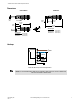
Sensor Programming
Two TEACH methods may be used to program the sensor:
• Teach individual minimum and maximum limits (Two-Point Static Teach), or
• Dynamic Teach for on-the-fly programming.
The sensor may be programmed either via its push button, or via a remote switch. Remote programming also may be used to disable the
push button, preventing unauthorized personnel from adjusting the programming settings. To access this feature, connect a normally
open switch between the sensor’s gray wire and dc common or connect the gray wire to a digital input (PLC).
NOTE: The impedance of the Remote Teach input is 3 kΩ.
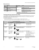
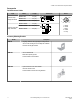
Programming is accomplished by following the sequence of input pulses (see Teaching Limits Using Two-Point Static TEACH on page
4). The duration of each pulse (corresponding to a push button “click”), and the period between multiple pulses, are defined as “T”:
0.04 seconds < T < 0.8 seconds
T-GAGE™ M18T Series Infrared Temperature Sensors
P/N 123698_web
Rev. A
www.bannerengineering.com - tel: 763-544-3164 3