
User Manual

DIP Switch Changes
Before making any changes to the DIP switch positions, disconnect
the power. For devices with batteries integrated into the housing,
remove the battery for at least one minute.
DIP switch changes will not be recognized if power isn't cycled to
the device.
Accessing the DIP Switches
To access the DIP switches, follow these steps:
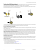
1. Unscrew the four screws that mount the cover to the bottom housing.
2. Remove the cover from the housing without damaging the ribbon cable or the pins the cable plugs into.
3. Gently unplug the ribbon cable from the board mounted into the bottom housing. For integrated battery models (no ribbon cable) and
Class I, Division 2 certified devices (ribbon cable is glued down), skip this step.
4. Remove the black cover plate from the bottom of the device's cover.
The DIP switches are located behind the rotary dials. After making the neces-
sary changes to the DIP switches, place the black cover plate back into posi-
tion and gently push into place. Plug the ribbon cable in after verifying that
the blocked hole lines up with the missing pin. Mount the cover back onto the
housing.
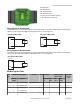
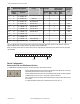
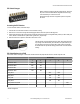
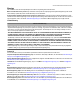
DIP Switch Settings for a DX85
Use the DIP switches 1 through 4 on the board to set the baud rate and parity and DIP switch 5 to set the rotary dial mode.
DIP Switches
1 2 3 4 5
Baud Rate: 19200 OFF* OFF*
Baud Rate: 38400 OFF ON
Baud Rate: 9600 ON OFF
Baud Rate: 19200 ON ON
Parity: None OFF* OFF*
Parity: Even OFF ON
Parity: Odd ON OFF
Parity: None ON ON
Rotary Dial Decimal Mode OFF*
Rotary Dial Hex Mode ON
* Default configuration
SureCross DX85 Modbus RTU Remote I/O Device
6 www.bannerengineering.com - tel: 763-544-3164 P/N 134324 rev. F