
User guide

I/O
Poin
t
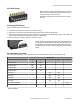
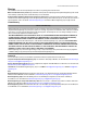
Modbus Holding Register I/O Type Units I/O Range Holding Register
Representation
Terminal
Block La-
bels
Gateway
or DX85
Any Node Min. Val-
ue
Max.
Value
Min.
(Dec.)
Max.
(Dec.)
5 5 5 + (Node# × 16)
6 6 6 + (Node# × 16)
7 7 7 + (Node# × 16) Reserved
8 8 8 + (Node# × 16) Device Message
9 9 9 + (Node# × 16) Discrete OUT 1–8 - 0 ** 0 255 DO1
10 10 10 + (Node# × 16)
11 11 11 + (Node# × 16)
12 12 12 + (Node# × 16)
13 13 13 + (Node# × 16)
14 14 14 + (Node# × 16)
15 15 15 + (Node# × 16) Control Message
16 16 16 + (Node# × 16) Reserved
The lower eight bits of the 16-bit unsigned register represent each of the eight digital outputs. Therefore, if all outputs are OFF (0) the
register contains 0x0000; if all outputs are ON (1) the register contains 0x00FF (255).
When your wireless network does not include a host system, the four input/eight output Node must be mapped to the eight input/four
output Gateway.
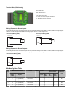
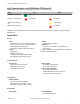
15 14 13 12 11 10 9 8 7 6 5 4 3 2 1 0
Outpu t 8
Outpu t 1
Outpu t 2
Device Configuration
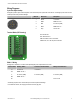
Setting the Slave ID on a DX85 Remote I/O Device
On a DX85 Modbus RTU Remote I/O device, use the rotary dials to set the device’s Slave ID.
In Rotary Dial Decimal Mode, the left dial acts as the left digit and the right dial acts as the right
digit, allowing the Slave ID to be set from 01 through 99.
In Rotary Dial Hex Mode, the left dial acts as the left digit and the right dial acts as the right digit,
allowing the Slave ID to be set from 01 through F7 for a total of 247 slaves.
The 12 I/O DX85 models use Rotary Dial Decimal Mode and do not have a DIP switch selection
for this option.
To configure the DX85 using the UCT, the DX85's Slave ID must be set to 01.
SureCross DX85 Modbus RTU Remote I/O Device
P/N 134325 rev. F www.bannerengineering.com - tel: 763-544-3164 5